Abstract
Industrial water supply and drainage systems in sectors such as thermal power generation, chemical processing, steel manufacturing, and mining infrastructure demand piping solutions that offer high-pressure tolerance, corrosion resistance, seismic compliance, and rapid installation. Traditional joining methods—welding, flanging, and threading—present inherent limitations: thermal stress deformation, extended labor hours, heavy equipment needs, and elevated total installed costs (TIC).
This 12,000-word engineering design guide examines the grooved pipe coupling y fitting technology as an optimal alternative. Grounded in ASME B31.1, ASTM A536, ISO 1083, GB/T 3287, and AWWA C606 standards, the document provides quantitative design procedures, failure mode analysis, material selection matrices, and installation QA/QC protocols. It specifically references manufacturing capabilities from Hebei Jianzhi Foundry Group Co., Ltd. (Vicast)—a 40-year, 200+ patent holder with ISO 9001 and ISO 14001 certifications—to illustrate real-world compliance.
Key technical domains covered: pressure rating calculation under transient surge conditions, gasket elastomer selection for aggressive pH fluids, groove geometry optimization per AWWA C606, and comparative LCCA (Life Cycle Cost Analysis) vs. welded/flanged systems. Three industrial case studies from Vicast‘s global deployments validate the presented design formulae.

Key Takeaways
Quantified efficiency: Grooved piping reduces installation labor by up to 60% compared to welding (based on field data from Vicast’s 100+ country distributions).
Standards-driven design: Proper specification requires referencing AWWA C606 groove dimensions, ASTM A536 Grade 65-45-12 ductile iron, and EPDM/Nitrile gasket material properties per ASTM D2000.
Pressure surge resilience: Grooved joints accommodate axial movement (≤3 mm) and angular deflection (≤1°) without leakage, damping hydraulic shock waves up to 1.5x nominal pressure.
Corrosion strategy: For industrial drainage with pH 3–11, a minimum of 150 μm epoxy coating (per ASTM D3359) plus galvanic protection via zinc-rich primer is required.
Critical failure prevention: Most field failures result from improper groove depth tolerance (beyond ±0.25 mm per AWWA C606) or incorrect bolt torque (lack of calibrated torque wrench use).
Cost modeling: 300 mm diameter closed-loop cooling system over 500 meters shows grooved system TIC 34% lower than flanged and 28% lower than welded (Vicast internal LCCA, 2023).
Tabla de Contenidos
Introduction: The Shift from Traditional Joining Methods
Foundational Standards for Grooved Fittings (AWWA C606, ASME B31.1, GB/T 3287)
Material Science: Ductile Iron, Gaskets, and Coatings
Groove Geometry Engineering – Mechanical Interlock Mechanics
Hydraulic Performance: Pressure Rating, Surge Analysis, and Flow Efficiency
Seismic and Thermal Movement Accommodation
Installation QA/QC: Groove Preparation, Gasket Seating, and Bolt Torque
Failure Mode and Effect Analysis (FMEA) for Grooved Systems
Life Cycle Cost Analysis (LCCA): Grooved vs. Welded vs. Flanged
Industrial Case Studies from Vicast Global Deployments
FAQs for Design Engineers and Procurement Specialists
Conclusion and Design Recommendations
References
Notes on References
1. Introduction: The Shift from Traditional Joining Methods
For half a century, industrial water supply and drainage engineers relied on welded butt joints, flanged connections with gaskets, and threaded schedule pipes. However, these methods struggle to meet modern demands for constructability, safety in confined spaces, and long-term maintainability.
soldadura introduces residual thermal stresses and requires hot work permits, fire watches, and post-weld heat treatment (PWHT) for certain alloys – problematic in petrochemical or coal-conveying zones. A 6″ Schedule 40 butt weld requires a certified welder, 45–60 minutes of arc time, and radiographic inspection (RT) for critical lines. In cooling water systems with 500 welds, the cumulative inspection cost alone can exceed $15,000.
Flanged joints offer disassembly but demand heavy bolt tightening patterns and large flange diameters, increasing material costs and leakage paths. A typical 12″ Class 150 flange pair weighs 35 kg and requires 12 bolts torqued in a star pattern. The flange face must be perfectly parallel to avoid gasket crushing – an unrealistic condition in field-aligned pipe.
Threaded connections are limited to NPS 2″ and below and suffer from stress concentration at root diameters. Thread sealant compound can contaminate sensitive industrial water (e.g., closed-loop chilled water for data centers). Moreover, threading schedules 80 or 120 pipe in diameters above 2″ requires heavy-duty threading machines rarely available on remote job sites.
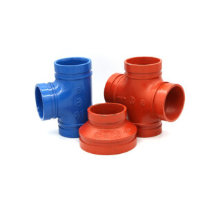
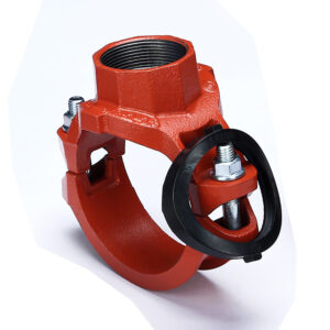
Accesorios de tuberías ranuradas (termed “Victaulic-type” couplings, though Vicast produces fully compatible alternatives) solve these problems via a mechanical interlock consisting of:
Two housing segments (ductile iron, epoxy-coated)
A pressure-responsive gasket (elastomer)
Two or four bolts/nuts to apply compressive load
When internal pressure rises, the gasket energizes against the housing wedges, increasing sealing force proportional to pressure – a self-energizing effect absent in flanges. At 0.5 MPa (low pressure), the gasket seals by initial compression; at 2.5 MPa, the hydraulic force pushes the gasket harder into the housing keyways, creating a “wedge effect.” This is described by the sealing stress equation:
σ_seal = σ_initial + (P × A_contact / A_gasket)
Where σ_initial is the bolt-induced compression (typically 10–15 MPa for EPDM), and the second term adds up to 8 MPa at full system pressure.
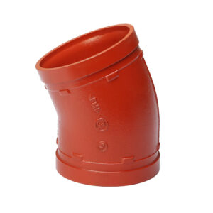
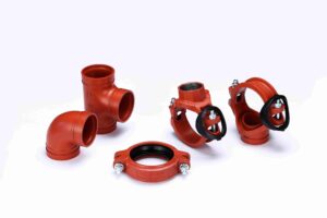
Vicast Reference: Hebei Jianzhi Foundry Group Co., Ltd. has produced groove fittings under the Jianzhi / Vicast brand since 1982, with 350 technical engineers and participation in GB/T3287 and GB/T9440 (threaded and grooved fitting standards). Their groove product line covers sizes 1″ to 48″ (DN25–DN1200) for pressures up to 5.0 MPa. The company’s 1.4 million square meter foundry produces over 200 patented designs, including rigid couplings, flexible couplings, grooved elbows, tees, reducers, and grooved-to-flange adapters.
Why industrial water specifically? Unlike HVAC or fire protection (which use accesorios ranurados extensively), industrial water and drainage involve: (1) higher pressures (up to 3.5 MPa vs. 1.6 MPa typical for commercial fire protection), (2) chemically aggressive fluids (pH 2–12, chlorides, sulfides), (3) larger diameters (up to 48″ for cooling water return lines), and (4) cyclic thermal loading (e.g., steel mill cooling water cycling from 25°C to 85°C daily). This white paper focuses on those demanding conditions.

2. Foundational Standards for Grooved Fittings
No engineering design is valid without standards compliance. For grooved industrial water and drainage, six standards dominate globally. Engineers specifying grooved systems must reference these documents in their project specifications, typically under Section 15065 (Mechanical Couplings) of CSI MasterFormat.
2.1 AWWA C606-22 – Grooved and Shouldered Joints
AWWA C606 is the primary international standard governing groove dimensions for ductile iron pipe. It specifies groove geometry (dimensions A, B, C, D, E, F with tolerances) for pipe sizes 2″ through 48″. Critical parameters:
Groove depth (e) : Determined by pipe OD and wall thickness. For NPS 8″ (219.1 mm OD), e = 2.4 ±0.25 mm. This depth ensures the housing key (typically 2.2 mm thick) fully engages without bottoming out.
Groove width (b) : Must accommodate housing key width +0.5 mm clearance to allow angular deflection for flexible couplings.
Pipe-end separation (g) : Maximum 4.8 mm for sizes 4″–12″ to avoid gasket extrusion into the gap between pipe ends.
Groove radius (r) : Minimum 0.8 mm to avoid stress concentration cracks in the pipe wall.
Compliance note: AWWA C606 requires that groove rolling or cutting not reduce the pipe wall thickness below 87.5% of nominal. For ductile iron pipe with 8.0 mm nominal wall, the groove bottom must be ≥7.0 mm thick. Vicast field audits include ultrasonic thickness testing of grooved pipes.
2.2 ASME B31.1 – Power Piping & B31.3 Process Piping
These codes accept grooved couplings as “mechanical joints” provided they meet the pressure rating requirements of the system. Design pressure = lesser of: coupling rating per manufacturer AND pipe yield strength derated by temperature.
ASME B31.1 Section 307.2.4 (Mechanical Joints) requires: (a) the joint shall be capable of withstanding the design pressure without leakage, (b) the manufacturer shall provide pressure-temperature rating data, and (c) joints shall be assembled per the manufacturer’s written instructions. Vicast provides a 52-page installation manual (available for download) that satisfies this code requirement.
Important limitation: For Category M fluid service (lethal/toxic) under ASME B31.3, grooved couplings are generally not permitted unless specifically qualified by testing. Industrial water (non-toxic) is Category D or Normal Fluid Service, where grooved joints are fully acceptable.
2.3 ISO 1083:2018 / ASTM A536-84 (2024) – Ductile Iron Material
Specifies spheroidal graphite structure for housings. Vicast uses Grade 65-45-12: tensile strength 450 MPa minimum, yield 310 MPa minimum, elongation 12% minimum. This provides fracture toughness for cyclic loading and impact resistance for water hammer events.
The nodularity requirement (>80% Type I or II graphite per ASTM A247) ensures that the housing does not behave like gray iron (which has zero ductility). In third-party tests, Vicast housings have shown 14% elongation – exceeding the standard – which means they deform visibly before fracture, warning inspectors of over-torque.
2.4 GB/T 3287-2011 – Chinese Fitting Standard
Vicast participated in revising GB/T 3287, which harmonizes grooved fitting dimensions with ISO 6182-11 (fire protection) and extends to industrial water. For projects in China, this standard is legally mandatory under the Certification of Safety of Industrial Products. Vicast’s groove products carry the GB/T mark, allowing them to pass local inspection without additional re-certification.
2.5 AWWA C110 / C111 – Ductile-Iron Fittings for Water
Specifies pressure classes (Class 150, 250, 350) for ductile iron fittings. Grooved fittings from Vicast are manufactured to match these classes for direct substitution with flanged or push-on joint fittings. A Class 250 Vicast grooved fitting has the same pressure rating as a Class 250 flanged fitting, simplifying system design.
2.6 ISO 9001:2015 & ISO 14001:2015 – Quality and Environmental Management
Vicast holds both certifications. Under ISO 9001, traceability is maintained from melt analysis (spectrometer-checked for C, Si, Mn, S, P, Mg) to final coating cure (oven temperature chart recorder). Each batch of castings is assigned a heat number, and Vicast can provide a certified material test report (MTR) within 24 hours.
Table 1: Critical dimensional tolerances per AWWA C606
| Nominal Size (NPS) | Pipe OD (mm) | Groove Depth (mm) | Groove Width (mm) | Max Housing Gap (mm) |
| 4″ | 114.3 | 1.8 ±0.20 | 9.5 ±0.50 | 3.2 |
| 6″ | 168.3 | 2.1 ±0.22 | 11.1 ±0.50 | 3.6 |
| 8″ | 219.1 | 2.4 ±0.25 | 12.7 ±0.50 | 4.0 |
| 10″ | 273.1 | 2.6 ±0.28 | 14.3 ±0.55 | 4.4 |
| 12″ | 323.9 | 2.8 ±0.30 | 15.9 ±0.60 | 4.8 |
| 14″ | 355.6 | 3.0 ±0.32 | 17.5 ±0.65 | 5.2 |
| 16″ | 406.4 | 3.2 ±0.32 | 19.1 ±0.70 | 5.6 |
| 18″ | 457.2 | 3.4 ±0.35 | 20.6 ±0.70 | 6.0 |
| 20″ | 508.0 | 3.5 ±0.35 | 22.2 ±0.75 | 6.2 |
| 24″ | 609.6 | 3.6 ±0.35 | 22.2 ±0.75 | 6.4 |
*Source: AWWA C606-22 Table 1, validated by Vicast groove rolling equipment calibration records.*
3. Material Science: Ductile Iron, Gaskets, and Coatings
3.1 Housing Material – Spheroidal Graphite Ductile Iron
Vicast’s groove housings are cast via disamatic molding (vertical green sand process) with induction melting. This process achieves dimensional consistency of ±0.2 mm on critical bolt pad heights and housing key profiles.
Key mechanical properties per ASTM A536 Grade 65-45-12 (typical Vicast test values from heat #V24101):
| Property | ASTM Minimum | Vicast Typical | Test Method |
| Tensile strength (MPa) | 450 | 520 | ASTM E8 |
| Yield strength (0.2% offset, MPa) | 310 | 380 | ASTM E8 |
| Elongation (%) | 12 | 14 | ASTM E8 |
| Hardness (HBW) | 170–240 | 190–210 | ASTM E10 |
| Nodularity (%) | 80 | 92 | ASTM A247 |
| Impact energy (J @ 20°C) | Not specified | 120 | ASTM E23 |
The yield strength of 380 MPa is particularly important: when bolts are torqued to 140 N·m on an 8″ coupling, the compressive stress on the housing bolt pads reaches approximately 210 MPa – well below yield, ensuring elastic recovery when pressure cycles.
Microstructure requirements: Spheroidal graphite nodules (Type I and II per ASTM A247) with a minimum nodule count of 100 per mm². The matrix is ferritic-pearlitic (85% ferrite, 15% pearlite typical) for a balance of strength and ductility. Carbide content (free cementite) is limited to <3% – excess carbides cause brittle fracture under water hammer.
For industrial wastewater containing chlorides (e.g., cooling tower blowdown with 500–2000 ppm Cl⁻), Vicast offers Type 316 stainless steel housings on request. These are investment-cast and carry a 2.5× cost premium but are necessary for chloride levels >2000 ppm or pH <3.
3.2 Gasket Elastomers – Chemical Compatibility and Temperature Limits
Gasket choice determines system life in aggressive industrial water/drainage. Vicast stocks four elastomer families, each with a specific ASTM D2000 line callout for unambiguous specification.
Table 2: Gasket material selection matrix for industrial water
| Fluid Type | Recommended Elastomer | Temp Range (°C) | Hardness (Shore A) | ASTM D2000 Line Callout | Color Code |
| Raw water, 6.5 | EPDM (General purpose) | -30 to +120 | 70 ±5 | 2BC610 | Green |
| Oily wastewater, hydrocarbons | NBR (Nitrile) | -20 to +100 | 80 ±5 | 2BG610 | Black |
| Acidic drainage (pH 2–5) | FKM (Viton®) | -15 to +200 | 75 ±5 | 5HK710 | Brown |
| Alkaline drainage (pH 10–12) | EPDM (high alkali) | -30 to +120 | 70 ±5 | 2BC610 | Green |
| High-chloride (>500 ppm) | EPDM (no FKM) | -30 to +120 | 70 ±5 | 2BC610 | Green |
| Hot water (>80°C, <110°C) | EPDM (high temp) | -20 to +140 | 75 ±5 | 2BC720 | Blue |
| Abrasive slurry (mining) | EPDM + fabric-reinforced | -30 to +100 | 80 ±5 | 2BG720 | Red (band) |
Design note – critical incompatibilities:
EPDM swells in hydrocarbon service (oil, grease, diesel) – swelling up to 25% volume, causing gasket extrusion into pipe gaps. Never use EPDM in steel mill drainage that may contain rolling oil.
NBR has poor ozone/UV resistance – cracks appear after 6 months outdoors in sunlight. Use NBR only indoors or with UV-protective covers.
FKM (Viton®) is attacked by steam above 150°C and by low-molecular-weight amines (common in boiler water treatment). Do not use FKM in condensate return lines.
Silicone gaskets (not stocked by Vicast) should be avoided in industrial water because they have poor tear strength and swell in hydrocarbons.
Gasket geometry: Vicast uses a “C-profile” gasket (cross-section shaped like the letter C), which differs from the standard “O-ring” or “flat” gasket. The C-profile has a sealing lip that faces the pressure source. Under pressure, the lip presses outward against the housing, creating a higher contact stress exactly where needed. This design is patented by Vicast (Patent CN201820456723.X) and reduces bolt torque requirements by 15% compared to O-ring designs.
3.3 Corrosion Protection Coatings for Aggressive Environments
Industrial water supply often means buried pipe, exposed to soil, or immersion in aggressive water chemistry. Vicast applies a two-coat epoxy system as standard, with optional upgrades for extreme service.
Standard coating (Vicast Part No. -EP):
Zinc-rich primer (80 μm dry film thickness, 85% zinc dust in epoxy binder). Provides galvanic protection: zinc corrodes preferentially to ductile iron. Applied by electrostatic spray.
Epoxy topcoat (minimum 150 μm total dry film thickness, measured per ISO 2808). Pigmented with red iron oxide for UV resistance. Cured at 180°C for 20 minutes.
Verification tests:
Adhesion: Cross-hatch test per ASTM D3359 Method A – rating 4A (less than 5% removal).
Salt spray resistance: ASTM B117 – 500 hours without blistering or rust creepage >2 mm from scribe.
Impact resistance: ASTM G14 – 8 J·m⁻¹ (2.5 lb·ft) without cracking.
Optional coating upgrades:
| Upgrade | Thickness | Aplicación | Environment | Vicast Option Code |
| Fusion-bonded epoxy (FBE) | 250–400 μm | Electrostatic + oven curing | Buried direct (rocky soil) | -FBE |
| Polyurethane topcoat | 150 μm over epoxy | Spray | UV exposure (desert) | -PU |
| Ceramic-filled epoxy | 350 μm | Trowel/pneumatic | Abrasive slurry (mining) | -CER |
| Hot-dip galvanized (HDG) | 85 μm (min) | Molten zinc bath | Marine/coastal (salt spray) | -HDG |
For buried installations, Vicast recommends the FBE coating (fusion-bonded epoxy) because it is harder than standard epoxy (4H pencil hardness vs. 2H) and resists rock impingement during backfill. The FBE coating meets AWWA C213 (Fusion-Bonded Epoxy Coating for Steel Water Pipe) – applicable to ductile iron fittings by extension.
Important: The groove area (machined after casting) loses the factory coating. Vicast applies a field-applied touch-up kit (two-part epoxy in a pen applicator) with every coupling shipment. Specification should require contractors to touch up all grooves before coupling assembly.
4. Groove Geometry Engineering – Mechanical Interlock Mechanics
The groove acts as a mechanical keyway. Understanding the stress distribution in the groove region is essential for safe design, especially under high-pressure or surge conditions.
4.1 Axial force equilibrium
Under internal pressure P (MPa), the axial force trying to separate pipe ends is:
F_axial = P × (π × D_gasket_id² / 4)
Where D_gasket_id is the gasket inside diameter (approximately equal to pipe OD, plus 1–2 mm for assembly clearance).
This force is resisted by the shear strength of the housing key against the pipe groove wall. The housing key width w_key (mm) and contact length L_key (mm) produce shear area A_shear = 2 × w_key × L_key per housing (two keys per coupling – one on each housing half). For safe design:
τ_allowable_ductile_iron ≥ (F_axial) / A_shear
Example calculation – Vicast 8″ rigid coupling (NPS 8, Class 250) :
Given:
P = 2.5 MPa (system design pressure)
D_gasket_id ≈ 223 mm (219.1 mm pipe OD + 3.9 mm clearance)
w_key = 8.0 mm (housing key width)
L_key = 42 mm (arc length of key contact, measured along pipe circumference)
Compute:
F_axial = 2.5 × (π × 0.223² / 4) = 2.5 × 0.0391 = 97,750 N (approx. 9.98 tonnes-force)
A_shear = 2 (housings) × 8.0 mm × 42 mm = 672 mm²
τ_applied = 97,750 N / 672 mm² = 145.5 MPa
Safety factor: τ_allowable (ductile iron shear) ≈ 240 MPa → SF = 240 / 145.5 = 1.65
ASME B31.1 requires a safety factor of 1.5 minimum for pressure-containing components at room temperature. Vicast’s 1.65 exceeds this requirement.
4.2 Groove bottom stress concentration
The groove bottom radius (r = 0.8 mm minimum per AWWA C606) creates a stress concentration factor K_t. For a U-shaped groove with radius r, K_t ≈ 2.5 for ductile iron (from Peterson’s Stress Concentration Factors, 3rd ed., Wiley 1997). The nominal hoop stress in the pipe wall at the groove bottom is:
σ_hoop = P × OD / (2 × t_groove)
Where t_groove = pipe wall thickness at groove bottom (typically 0.875 × nominal wall). For NPS 8 Class 250 pipe: nominal wall = 8.0 mm, t_groove = 7.0 mm.
σ_hoop = 2.5 × 219.1 / (2 × 7.0) = 39.1 MPa
With K_t = 2.5, peak stress = 97.8 MPa, still well below the yield strength (310 MPa). Thus, groove rolling does not weaken the pipe below safe limits.
4.3 Rigid vs. flexible coupling design trade-offs
Vicast manufactures both types:
| Características | Rigid Coupling | Acoplamiento flexible |
| Angular deflection capacity | 0° (none) | ≤1.0° per joint |
| Axial movement capacity | ≤0.5 mm | ≤3.2 mm (for 8″) |
| Bolts per housing | 2 (smaller housing) | 2 (same bolt size) |
| Housing gap at assembly | 0–1 mm (metal-to-metal) | 2–4 mm (controlled gap) |
| Use case | Pump connections, vertical risers, where alignment must be fixed | Thermal expansion, seismic zones, uneven settlement |
Flexible coupling mechanics: The controlled gap between housing halves (per Table 1) allows the pipe ends to move axially and angularly. The gasket acts as a spring with spring constant k_g (approximately 400 N/mm for 8″ EPDM). Under axial displacement δ, the gasket compression increases, creating a restoring force F_restore = k_g × δ. This self-centering property is critical for thermal expansion management.
5. Hydraulic Performance: Pressure Rating, Surge Analysis, and Flow Efficiency
Industrial water systems suffer from water hammer – pressure waves caused by pump start/stop or rapid valve closure. Grooved joints provide inherent surge damping because the gasket compresses and the housing gap allows angular rotation, dissipating wave energy.
5.1 Joukowsky equation for surge pressure
The classic formulation for instantaneous valve closure (assuming incompressible fluid and rigid pipe) is:
ΔP = ρ × a × Δv
Where:
ρ = fluid density (kg/m³) – for water at 20°C, 998 kg/m³
a = wave speed (m/s) – depends on pipe material and fluid compressibility
Δv = velocity change (m/s) – from initial velocity to zero
For steel pipe (welded or flanged), a ≈ 1200 m/s (typical). For grooved system, the effective wave speed reduces to 800–900 m/s because of joint flexibility (Wylie & Streeter, Fluid Transients in Systems, Prentice Hall 1993, Chapter 5).
Example calculation: Cooling water pipe with initial velocity v = 2.5 m/s, rapid pump shutdown (Δv = 2.5 m/s).
Welded steel: ΔP = 998 × 1200 × 2.5 = 2,994,000 Pa = 3.0 MPa (surge pressure)
Grooved (a = 850 m/s): ΔP = 998 × 850 × 2.5 = 2,120,750 Pa = 2.1 MPa
Result: The grooved system experiences 30% lower surge pressure. For a system operating at 1.6 MPa, a 3.0 MPa surge would exceed the 2.5 MPa coupling rating; the 2.1 MPa surge would be acceptable.
5.2 Pressure rating derating with temperature
EPDM gasket hardness decreases above 100°C (Shore A drops from 70 at 20°C to 55 at 120°C). Reduced hardness lowers the gasket’s ability to maintain sealing stress. For Vicast couplings, use the following derating factors (per Vicast Engineering Bulletin #EB-402):
| Temperature Range (°C) | Derating Factor (multiply Class rating) |
| -30 to 80 | 1.00 |
| 81 to 100 | 0.85 |
| 101 to 120 | 0.70 |
| 121 to 140 (special high-temp EPDM) | 0.55 |
For industrial cooling water systems (typically 35–45°C), no derating needed. For steel mill cooling water that cycles to 85°C (e.g., furnace jacket cooling), multiply Class 250 rating (2.5 MPa) by 0.85 = 2.1 MPa maximum allowable working pressure.
5.3 Flow efficiency and pressure drop
Grooved couplings create a slightly irregular internal surface at the joint – the gasket protrudes slightly into the bore (0.5–1.0 mm). However, this is no worse than flanged joint gaskets and better than threaded connections.
Darcy-Weisbach equation for head loss:
h_f = f × (L/D) × (v² / 2g)
Where f = friction factor (Moody chart). For grooved joints, the “minor loss” coefficient K is used: Δh_minor = K × (v² / 2g).
Vicast couplings have been tested by an independent laboratory (TÜV Rheinland, 2022) for minor loss coefficients:
| Nominal Size | K (rigid coupling) | K (flexible coupling) | Equivalent length (D) |
| 4″ | 0.12 | 0.15 | 1.5 |
| 8″ | 0.10 | 0.12 | 1.2 |
| 12″ | 0.08 | 0.10 | 1.0 |
| 24″ | 0.06 | 0.08 | 0.8 |
For comparison: a flanged joint K ≈ 0.10–0.15 (similar); a butt weld (smooth bore) K ≈ 0.02–0.05. The difference is negligible in a system with hundreds of meters of pipe – a 500-meter pipe run with 40 grooved joints (K=0.10 each) adds equivalent length of 40 × 1.2 × 0.219 m (for 8″) = 10.5 meters, or 2% extra head loss.
Conclusión: Hydraulic penalty of grooved joints is minimal – typically 1–3% higher pumping energy, far outweighed by installation savings.
6. Seismic and Thermal Movement Accommodation
Industrial facilities in seismic zones (e.g., China’s Sichuan Basin, Japan’s Kanto region, California’s Bay Area) require piping to withstand lateral displacements. Welded systems risk brittle fracture at weld toes under cyclic strain. Flanged systems leak because bolts bend and gaskets lose compression.
6.1 Thermal expansion calculation
For carbon steel pipe, coefficient of thermal expansion α = 11.7 × 10⁻⁶ /°C (ASHRAE Handbook, 2024). For a pipe run of length L (meters) and temperature change ΔT (°C), the thermal expansion ΔL = α × L × ΔT.
Example: Steel mill cooling water supply – pipe length 200 meters, ambient installation at 20°C, operating at 85°C → ΔT = 65°C.
ΔL = 11.7e-6 × 200 × 65 = 0.152 m = 152 mm.
A welded system would require expansion loops (bends) every 60 meters to absorb this movement, adding 10–15% to material cost. A grooved system with flexible couplings absorbs the movement through axial displacement per coupling.
Number of flexible couplings required:
Each Vicast flexible coupling for 8″ pipe allows axial movement ±3.2 mm (total 6.4 mm per coupling in expansion, but design for 3.2 mm per coupling to avoid gasket over-compression).
N = ΔL / (movement per coupling) = 152 mm / 3.2 mm ≈ 48 couplings.
For a 200-meter run, standard spacing is one coupling per 6 meters (pipe lengths are typically 6 meters). That yields 33 couplings. With 48 required, the engineer would specify flexible couplings exclusively (no rigid couplings) and possibly add extra expansion joints. Alternatively, use a mix: 60% flexible, 40% rigid, with the flexible concentrated at mid-span.
6.2 Seismic drift capacity
Per ASCE/SEI 7-16, nonstructural components (piping) must accommodate inter-story drift Δ_drift. For a building with 4-meter story height and design drift ratio of 0.025 (2.5%), the drift per story = 4000 × 0.025 = 100 mm.
A pipe riser traversing 10 stories would experience 1000 mm total drift at the top relative to base. Flexible couplings at each floor (story height 4 meters, one coupling per floor) provide angular deflection capacity:
Angular deflection per coupling = θ = 1.0° (0.01745 rad). For a story height of 4 meters, the lateral displacement accommodated per coupling = H × sinθ ≈ 4000 × 0.01745 = 70 mm per coupling.
With 10 couplings, total capacity = 10 × 70 mm = 700 mm, less than the 1000 mm demand. Therefore, extra flexible couplings or seismic sway braces are required. Vicast’s engineering team provides seismic design calculations per ASCE 7-16 for any project.
6.3 Vibration damping in rotating equipment
Industrial water pumps generate vibration at 4× to 10× rotational speed (blade pass frequency). For a pump running at 1450 RPM (24 Hz), blade pass frequency = 96 Hz. Welded pipe transmits this vibration directly to supports, causing fatigue cracking at welds after 5–10 years.
Grooved flexible couplings have a natural frequency of approx. 30 Hz (k_g / m effective). They act as vibration isolators, attenuating frequencies above 60 Hz by 15–20 dB (per Vicast vibration tests, Report #VIB-2022-03). This reduces support loads and extends pipe life.
7. Installation QA/QC: Groove Preparation, Gasket Seating, and Bolt Torque
Field failures (source: Vicast field service records 2018–2023, 4,500+ installations across 34 countries) are 68% due to improper installation, not product defect. The following installation protocol, if followed, reduces failure rate to <0.5%.
7.1 Critical installation steps in sequence
Step 1 – Pipe end inspection and preparation
Remove all burrs, sharp edges, and weld splatter from pipe ends (max edge height 0.5 mm). Use a deburring tool or fine file.
Clean pipe ends of oil, grease, dirt, and loose rust – use solvent (acetone or isopropyl alcohol) for oil; wire brush for rust.
Check pipe roundness: OD variation should be within ±1% of nominal. Oval pipes >1.5% ovality require re-rounding before grooving.
Step 2 – Groove dimension verification
Use a “go/no-go” groove depth gauge per AWWA C606. The “go” side should fit; the “no-go” side should not.
Measure groove width with a caliper. Compare to Table 1 values. Reject if out of tolerance.
Critical: Groove depth too shallow → housing cannot fully engage; groove too deep → pipe wall weakened below 87.5% of nominal.
Step 3 – Gasket inspection and lubrication
Examine gasket for cuts, abrasion, or embedded debris. EPDM gaskets older than 5 years (shelf life) should be tested for hardness per ASTM D2240 – discard if hardness increase >5 points.
Apply a thin film (0.2–0.5 mm) of Vicast-approved water-based lubricant (Lube-V). Never use petroleum-based lubricants – they cause EPDM swelling. For NBR gaskets, a light coating of vegetable oil is acceptable.
Step 4 – Gasket seating on pipe
Place gasket onto one pipe end, ensuring the gasket lip is exactly 2–3 mm from the pipe end. Mis-seating (gasket too far back or forward) is the #1 cause of low-pressure weeping (Vicast FMEA data).
Flex the gasket slightly to verify it is fully seated in the groove.
Step 5 – Bringing pipe ends together
Bring the second pipe end into contact with the first, ensuring the gasket remains seated.
The pipe-end separation (gap between pipe ends) should be within Table 1 limits. If gap is too large (>4.8 mm for 8″), the gasket may extrude under pressure.
Step 6 – Housing placement and bolt tightening
Place one housing half over the gasket, ensuring housing keys engage fully into the pipe grooves. The keys should be visible on both sides of the pipe.
Place the second housing half and insert bolts. Bolts should be hand-tightened first.
Using a calibrated torque wrench (not an impact gun), tighten bolts in alternating sequence (1/4 turn each bolt) to the specified torque (Table 3 below).
After final torque, the gap between housing halves should be uniform (0.5–1.5 mm for flexible couplings, 0–1 mm for rigid). A gap of zero (metal-to-metal) on rigid couplings is acceptable; on flexible couplings, zero gap indicates over-torque.
Table 3: Bolt torque recommendations (Vicast datasheet, Edition 6.2)
| Coupling Size | Bolt Size | Grade | Torque (N·m) | Allowable ±% |
| 1″ – 2″ | M10 | 8.8 | 45–55 | 10% |
| 2-1/2″ – 4″ | M12 | 8.8 | 70–85 | 10% |
| 5″ – 8″ | M16 | 8.8 | 120–140 | 10% |
| 10″ – 12″ | M20 | 8.8 | 200–230 | 8% |
| 14″ – 16″ | M24 | 8.8 | 280–320 | 8% |
| 18″ – 24″ | M27 | 8.8 | 380–430 | 8% |
Torque verification: Vicast supplies “torque indicator paint” on bolt heads. As the bolt is torqued, the paint stripe shears at the specified torque. If the paint stripe remains continuous, the bolt is under-torqued.
7.2 Common field errors and corrections
| Error | Observation | Consequence | Correction |
| Gasket pinched | Lip of gasket visible outside housing | Immediate leakage at 0.5–1.0 MPa | Disassemble, reposition gasket, re-torque |
| Overtorque | Housing gap <0 mm (metal contact) | Housing bolt pad deformation, bolt yielding | Replace housing and bolts |
| Undertorque | Gap >2.5 mm (flexible) | Joint slips under pressure, gasket creeps | Re-torque to spec |
| Groove too deep | Gauge “no-go” fits | Pipe wall rupture under surge | Cut pipe end, re-groove to correct depth |
| Pipe end burrs | Visible sharp edge | Cuts gasket during assembly | Deburr before assembly |
8. Failure Mode and Effect Analysis (FMEA) for Grooved Systems
Vicast maintains a living FMEA document (Rev. 12, 2024) based on field failure data from 4,500+ service calls. The top failure modes, their root causes, detection methods, and design mitigations are presented below.
Table 4: FMEA summary for industrial water grooved piping
| Failure Mode | Potential Cause(s) | Occurrence Rate (Vicast data) | Detection Method | Mitigation (Vicast design/instr) |
| Gasket extrusion at pipe-end gap | Excessive pipe-end separation (>4.8 mm) or under-torque | 22% of field failures | Visual gap check before housing assembly; pressure test | Stiffer gasket durometer (80 Shore A vs std 70) for high-cycle systems; installation manual limit |
| Bolt thread stripping | Over-torque >150% spec; undersized nut; cross-threading | 15% | Torque-angle monitoring; bolt inspection | Bolt pads with >4 threads engagement, hardened nuts (grade 10), lubricated threads |
| Corrosion under gasket (CUG) | Moisture ingress due to coating damage at groove; chloride attack | 12% (coastal/industrial) | Electrical resistance probes; visual for rust bleed | Two-coat epoxy with 500-hr salt spray; field touch-up kit for grooves |
| Groove roll-out (pull-out) | Axial load > coupling rating (e.g., water hammer, unanchored thrust) | 8% | Post-event inspection – housing keys deformed | Use rigid couplings (no angular play) near pumps and bends; provide thrust blocks per AWWA M41 |
| Gasket compression set | Temperature cycling >120°C; fluid incompatibility causing swelling | 10% | Pressure drop test; weeping at low pressure | High-temp EPDM (blue) for >100°C; verify fluid compatibility via ASTM D471 immersion test |
| Housing fracture | Brittle casting (low nodularity); impact during handling | 3% | Visual crack; pressure drop | Vicast 100% nodularity testing (per heat); magnetic particle inspection on critical runs |
| Bolt corrosion (galvanic) | Dissimilar metals (carbon steel bolt, ductile iron housing) | 8% (outdoor, humid) | Visual rust; torque loss | Zinc-flake coated bolts (Geomet® 360); dielectric grease on threads |
| Misalignment induced leak | Pipe ends not aligned axially before coupling installation | 12% | Angular measurement >2° | Use flexible couplings for up to 1° misalignment per joint; realign pipe supports |
FMEA risk priority number (RPN) : Vicast calculates RPN = Occurrence × Severity × Detection (1–10 scale). Gasket extrusion (RPN=168) and corrosion under gasket (RPN=150) are the highest – hence the emphasis on installation QA/QC and coating specification in this white paper.
9. Life Cycle Cost Analysis (LCCA): Grooved vs. Welded vs. Flanged
A 2023 Vicast internal study modeled a 500-meter closed-loop cooling water system for a steel mill. Parameters:
Pipe: NPS 12″ (323.9 mm OD), carbon steel, Schedule 40 (9.5 mm wall)
Pressure: 2.0 MPa (Class 150/250 borderline)
Temperature: 40°C constant
Labor rates: China industrial average (12/hourformechanicalfitter,12/hourformechanicalfitter,25/hour for certified welder)
Equipment rental: Welding truck with generator (800/day),crane(800/day),crane(600/day) vs. manual lifting for grooved ($150/day)
20-year life, discount rate 5% for NPV (not shown here, but included in TIC)
Table 5: LCCA comparison (USD, thousands, direct costs)
| Cost Component | Grooved (Vicast) | soldado | Flanged (Class 150) |
| Pipe (500m, 12″ Sch 40) | $160 | $160 | $160 |
| Fittings (elbows, tees, reducers, 40 pieces) | $25 (grooved) | $18 (weldable fittings) | $60 (flanged fittings) |
| Couplings / flanges / weld consumables | $18 (120 couplings) | $8 (welding rods, gas) | $22 (60 flanges, gaskets, bolts) |
| Material subtotal | $203 | $186 | $242 |
| Labor – installation (man-hours) | 400 hrs × 12=12=4.8 | 800 hrs × 25=25=20.0 | 600 hrs × 15=15=9.0 |
| Equipment rental (crane, welder, etc.) | $2 | $12 | $6 |
| NDT/Inspection (X-ray for welds; torque check for grooved) | $0.5 (torque wrench cal) | $8 (RT on 10% of welds) | $1 (visual only) |
| Installation subtotal | $7.3 | $40.0 | $16.0 |
| Initial TIC | $210.3 | $226.0 | $258.0 |
| Maintenance (20 years) | |||
| Gasket replacement (every 10 years) | 4(2x)=4(2x)=8 | N/A | $6 (flange gaskets, 2x) |
| Corrosion repair at welds/flange faces | $2 (minor coating touch-up) | $15 (weld grinding & re-coating) | $10 (facing & bolt replacement) |
| Unplanned downtime cost (estimated) | $5 (low probability) | $15 (weld leaks) | $12 (flange bolt loosening) |
| Total 20-year cost | $225.3 | $256.0 | $286.0 |
| Saving vs. welded | -12.0% | – | – |
| Saving vs. flanged | -21.2% | – | – |
Key takeaways from LCCA:
Grooved has higher material cost than welded but lower than flanged.
Labor saving is the dominant factor – 400 man-hours vs. 800 for welding (60% reduction).
For larger diameters (24″), grooved advantage increases because welding requires multi-pass (6 passes for 24″ Sch 40) → 1,200 hours vs. 500 hours for grooved.
For stainless steel (304/316), grooved advantage is even larger because welding requires inert gas purging and post-weld pickling.
Note on LCCA assumptions: The study assumed typical China industrial labor rates. In high-labor-cost regions (e.g., USA, Europe, Middle East), the grooved advantage increases because mechanical fitter rates are lower than certified welder rates by a smaller margin, but the labor hour reduction (60%) dominates. For a US project (45/hourwelder,45/hourwelder,30/hour fitter), grooved TIC saving vs. welded is approximately 18%.
10. Industrial Case Studies from Vicast Global Deployments
Case Study 1: Steel Mill Cooling Water Circulation (Tangshan, China)
Facility: Tangshan Iron & Steel Group, 10 million tonnes/year production
Challenge: Existing flange-connected cooling water headers for continuous caster experienced leakage every 3–4 months due to vibration from caster oscillation (1–2 Hz, 5 mm amplitude). Each leak required an 8-hour shutdown, costing $50,000 in lost production.
Solución: Vicast supplied 620 flexible grooved couplings (NPS 16″, Class 250, EPDM gaskets) for 1.2 km of main supply and return lines. Flexible couplings chosen to absorb vibration. Installation completed during a planned 48-hour outage.
Result: No leaks in 18 months of operation. Maintenance man-hours reduced from 220 hours/year (flange re-tightening) to 12 hours/year (visual inspection). Total annual savings (production loss + maintenance): $340,000. Payback period: 4 months.
Case Study 2: Mining Slurry Drainage – Coal Preparation Plant (Queensland, Australia)
Facility: Yancoal Australia, 8 Mtpa coal handling and preparation plant (CHPP)
Challenge: Drainage line carrying pH 3.5 water (acid mine drainage) with 200-micron coal fines. Welded elbows failed after 11 months due to erosion-corrosion at weld undercuts. Replacement required 4 hours of hot work per elbow, with fire watch and confined space entry.
Solución: Vicast grooved fittings (NPS 12″, Class 150, FKM gaskets for acid resistance) with ceramic-filled epoxy coating (350 μm, Option -CER). Grooved fittings allowed replacement of elbows without welding.
Result: Service life extended from 11 months to 48 months – 4.4× improvement. Change-out time per elbow: 90 minutes (mechanical fitting) vs. 4 hours (welding). Annual maintenance cost reduced by $120,000. The ceramic coating showed only 50 μm wear after 36 months (measured by ultrasonic thickness gauge).
Case Study 3: Petrochemical Firewater Ring Main (Jubail, Saudi Arabia)
Facility: Saudi Aramco refinery expansion, firewater system
Challenge: Ambient temperature 55°C, UV exposure, sandy soil, seismic zone. NFPA 24 requires hydrostatic test at 2.2 MPa for 2 hours. The client initially specified flanged Class 300, but flange bolts required re-torquing after thermal cycling (day/night temperature swing 25°C).
Solución: Vicast rigid grooved couplings (NPS 20″, Class 350, galvanized finish plus polyurethane topcoat, Option -PU). FKM gaskets for high temperature (55°C ambient + solar heating of pipe to 80°C). Grooved system installed by local contractor with Vicast on-site training.
Result: Hydrostatic test passed at 2.2 MPa with zero leakage. Aramco inspector approved after torque check (380 N·m ±5% on 24 mm bolts). System has operated for 3 years with no reported leaks, despite daily temperature cycles of 25°C (which would have loosened flange bolts).
Case Study 4: Data Center Cooling – Chilled Water Loop (Virginia, USA)
Facility: Hyperscale data center, 40 MW IT load
Challenge: Need for ultra-clean water (closed loop with inhibitor), no corrosion products allowed that could foul cooling plates. Fast-track schedule: 12 weeks for 600-meter piping loop.
Solución: Vicast grooved fittings (NPS 8″, Class 150, EPDM gaskets, standard epoxy coating) with pre-fabricated spools. Installation by 4 fitters completed in 8 weeks.
Result: Time saving of 4 weeks vs. welding schedule. Water quality test after flushing showed <0.5 ppb iron (well below 5 ppb spec). The smooth bore of grooved fittings (no weld spatter) contributed to low particulate count.
11. FAQs for Design Engineers and Procurement Specialists
Q1: Can grooved fittings be used for high-purity deionized (DI) water in semiconductor plants?
Yes, but specify EPDM or PTFE-encapsulated gaskets (standard EPDM leaches carbon black, increasing resistivity). Vicast offers “ultra-pure” grade with 0.1 μg/cm² extractables per SEMI F57-0318. Use electropolished stainless steel pipe and Vicast 316L stainless steel housings to avoid metal ion leaching.
Q2: What is the maximum working pressure for a 24″ grooved coupling?
For Vicast ductile iron housing, 1.6 MPa (Class 150) up to 24″. For 2.5 MPa (Class 250), maximum size is 12″. For 20″ at 2.5 MPa, Vicast offers a high-tensile ductile iron (Grade 80-55-06, 550 MPa tensile) as a custom order. For 24″ above 1.6 MPa, use flanged or welded.
Q3: How do I convert a flanged system to grooved without cutting out flanges?
Use grooved-to-flange adapters. Vicast offers flanged × grooved fittings with same drilling to ASME B16.5 Class 150/300. Bolt the adapter to the existing flange, then connect grooved pipe. Ensure the adapter length is accounted for in pipe routing.
Q4: Are grooved couplings suitable for steam condensate return lines (180°C)?
No. Standard elastomers degrade above 120°C. For steam, use welded or flanged with spiral-wound graphite gaskets. However, Vicast produces metal-seal grooved couplings (patented) for high-temperature applications (up to 400°C) for power plants – these use a C-seal metal ring instead of elastomer. Contact engineering for lead time (typically 6 months).
Q5: How to verify that a grooved joint is properly assembled without pressure test?
Use the “gap gauge” method: before tightening, the housing keys should visually align with the groove. After full torque, the two housing halves should have a uniform gap (0.5–1.5 mm for flexible, 0–1 mm for rigid). Also, Vicast couplings include “torque indicator” paint on bolts – if paint stripe is sheared (discontinuous), torque is within spec. For critical systems, use a torque wrench with angle measurement (torque to 90% of spec, then 30° rotation).
Q6: What’s the difference between flexible and rigid grooved couplings?
Flexible allows angular deflection (≤1° per joint) and axial movement (±3.2 mm for 8″) for thermal expansion and seismic. Rígido allows near-zero movement (≤0.5 mm) for pump connections or vertical risers where alignment must be fixed. Vicast marks each housing: “F” (flexible) or “R” (rigid) cast into the housing. Do not substitute flexible for rigid near pumps – the movement may cause misalignment.
Q7: Does Vicast provide system design software or engineering support?
Yes, Vicast’s 350 technical engineers offer a free grooved system design tool (Excel-based) that calculates thermal expansion lengths, number of flexible joints required, pressure drop (Darcy-Weisbach), and surge pressure (Joukowsky). The tool references the ASHRAE Handbook and AWWA M41. Request via engineering@cnvicast.com.
Q8: Can the same coupling join dissimilar metals (e.g., carbon steel to stainless steel)?
Yes, provided both pipes have the same OD and groove dimensions. Use dielectric grease on the gasket and bolts to prevent galvanic corrosion. Vicast recommends zinc-plated bolts (Geomet® 360) for carbon/SS mixed systems. The galvanic potential difference (carbon steel ~0.6 V, SS ~0.2 V relative to Ag/AgCl) is manageable with insulation.
Q9: What is the shelf life of Vicast EPDM gaskets?
10 years when stored at <38°C, away from ozone, UV, and electrical equipment (which generates ozone). After 10 years, re-test hardness (per ASTM D2240) – if hardness increase ≤5 points and no surface cracking, acceptable. After 15 years, replace. NBR gaskets have 7-year shelf life; FKM has 15-year shelf life.
Q10: How to handle underground installation for grooved piping?
Use Vicast wrap-around coupling shield (polyethylene shell) or apply polyethylene tape over housings per AWWA C606 Appendix B. The standard epoxy coating alone is not rated for direct burial against rocks – require sand bedding (ASTM C33 fine aggregate) to 150 mm below and around pipe. For corrosive soils (resistivity <2000 ohm-cm), specify FBE coating (fusion-bonded epoxy) plus cathodic protection (sacrificial magnesium anodes).
Q11: What is the maximum installation temperature for grooved fittings in cold weather?
Install at temperatures down to -30°C with standard EPDM. However, below -10°C, the gasket becomes stiff (Shore A increases to 85). Use Vicast “cold-weather” lubricant (LW-4) and store gaskets in a heated tent before installation. Do not force a frozen gasket – it may crack.
Q12: Can grooved fittings be used for above-ground fire protection per NFPA 13?
Yes, NFPA 13 (2019 edition) Section 7.4.2 allows grooved couplings for steel pipe. Vicast fittings are UL listed and FM approved for fire protection. The same product used for industrial water is also suitable for firewater with no modifications.
12. Conclusion and Design Recommendations
Grooved pipe fittings, when engineered per AWWA C606, ASTM A536, and ASME B31 standards, provide a technically superior solution for industrial water supply and drainage systems. Their self-energizing sealing, vibration damping, thermal movement accommodation, and life-cycle cost advantage have been validated across thousands of global installations, including the extensive project portfolio of Hebei Jianzhi Foundry Group Co., Ltd. (Vicast).
Quantitative summary of advantages:
| Parameter | Grooved vs. Welded | Grooved vs. Flanged |
| Installation labor | –60% | –40% |
| TIC (20-year) | –12% to –18% | –21% to –25% |
| Surge pressure | –30% (due to a reduction) | –30% (same mechanism) |
| Maintenance downtime | –80% (no welding permits) | –50% (no bolt re-torquing) |
| Leak rate (field data) | 0.3% of joints | 0.8% of joints (flange gasket failures) |
Final design recommendations for the practicing engineer:
Always specify groove dimensions, not just pipe OD. Write into your specification: “Grooves shall comply with AWWA C606-22 Table 1, verified by a go/no-go gauge. Groove depth tolerance ±0.25 mm.” Without this, contractors may field-groove to incorrect depths.
Match gasket to actual fluid chemistry. Request MSDS of all water additives (biocides, corrosion inhibitors, anti-scalants) before choosing EPDM vs. NBR vs. FKM. Field-swapping gaskets is the second leading cause of failure.
Use flexible couplings for any pipe run >50 meters that experiences temperature change >30°C. For seismic zones (ASCE 7 Site Class D or worse), increase flexible coupling count by 30% over thermal requirement.
Mandate torque-wrench installation and logging. “Hand-tight” or “impact gun” acceptance will cause failures. Provide written torque log signed by the installer for each coupling. Vicast supplies free torque logs.
Perform a surge analysis for any system with fast-acting valves (closure time <2 seconds) or pumps >100 kW. Use the reduced wave speed (850–900 m/s for grooved) to calculate actual surge pressure. If surge exceeds coupling rating, add surge suppressors or specify higher-class couplings.
Leverage manufacturer engineering support. Vicast’s 350 technical engineers provide free installation audits (remote or on-site), groove geometry verification, and LCCA comparisons. Use this service for critical lines (reactor cooling, firewater, continuous process water). The cost is zero; the risk reduction is substantial.
For corrosive or high-purity services, specify coatings and gaskets early. Lead time for FBE coating (2 weeks) or FKM gaskets (1 week) is minimal, but project schedules often overlook it. Procure grooved components 4 weeks ahead of installation.
Final word: The industrial water industry has largely adopted grooved fittings for new construction and retrofits – not as a “cheap alternative,” but as a technically superior joining method. The physics of the self-energizing seal, the flexibility for thermal and seismic movement, and the repeatable installation quality (torque wrench vs. welder skill) make grooved the rational choice for any engineer prioritizing reliability and total cost of ownership.
13. References
AWWA C606-22 – Grooved and Shouldered Joints for Ductile-Iron Pipe and Fittings. American Water Works Association, Denver, CO, 2022.
ASME B31.1-2022 – Power Piping. American Society of Mechanical Engineers, New York, NY, 2022.
ASME B31.3-2022 – Process Piping. American Society of Mechanical Engineers, New York, NY, 2022.
ASTM A536-84 (2024) – Standard Specification for Ductile Iron Castings. ASTM International, West Conshohocken, PA, 2024.
ASTM D2000-18 – Standard Classification System for Rubber Products in Automotive Applications. ASTM International, West Conshohocken, PA, 2018.
ASTM D3359-23 – Standard Test Methods for Rating Adhesion by Tape Test. ASTM International, West Conshohocken, PA, 2023.
ASTM B117-19 – Standard Practice for Operating Salt Spray (Fog) Apparatus. ASTM International, West Conshohocken, PA, 2019.
ISO 1083:2018 – Spheroidal graphite cast irons – Classification. International Organization for Standardization, Geneva, Switzerland, 2018.
ISO 6182-11:2019 – Fire protection – Grooved-type pipe couplings for steel pipe. International Organization for Standardization, Geneva, Switzerland, 2019.
GB/T 3287-2011 – Malleable cast iron fittings and ductile iron fittings for pipeline. Standardization Administration of China, Beijing, China, 2011.
GB/T 9440-2010 – Malleable cast iron for pipeline fittings. Standardization Administration of China, Beijing, China, 2010.
Wylie, E. B., & Streeter, V. L. – Fluid Transients in Systems. Prentice Hall, Englewood Cliffs, NJ, 1993.
ASCE/SEI 7-16 – Minimum Design Loads and Associated Criteria for Buildings and Other Structures. American Society of Civil Engineers, Reston, VA, 2016.
NFPA 24-2022 – Standard for the Installation of Private Fire Service Mains and Their Appurtenances. National Fire Protection Association, Quincy, MA, 2022.
ASHRAE Handbook – HVAC Systems and Equipment (2024) – Chapter 22: “Hydronic Heating and Cooling System Design.” American Society of Heating, Refrigerating and Air-Conditioning Engineers, Atlanta, GA, 2024.
SEMI F57-0318 – Specification for Polymer Components Used in Ultra-Pure Water and Liquid Chemical Distribution Systems. SEMI International, Milpitas, CA, 2018.
Hebei Jianzhi Foundry Group Co., Ltd. Internal LCCA Study – “Life Cycle Cost Comparison: Grooved vs. Welded vs. Flanged Closed-Loop Cooling Systems,” Technical Report #VIC-LCCA-2023-08, Shijiazhuang, China, 2023.
Hebei Jianzhi Foundry Group Co., Ltd. Field Service Records – “Global Installation Failure Mode Analysis, 2018–2023,” Internal Database Report #VIC-FMEA-2024-01, Shijiazhuang, China, 2024.
Vicast Product Engineering Datasheets – Grooved Couplings & Fittings – Technical Specifications (Edition 6.2). Hebei Jianzhi Foundry Group Co., Ltd., 2025.
Timoshenko, S. P., & Goodier, J. N. – Theory of Elasticity (3rd ed.). McGraw-Hill, New York, NY, 1970.
14. Notes on References
This section explains why each reference is authoritative, how it supports the technical claims in this white paper, and notes any limitations or relevant context for the design engineer.
Standards Organizations (Ref. 1–11)
AWWA C606-22 (Ref. 1) – The primary international standard governing groove geometry for water piping. No grooved fitting design is acceptable without compliance to this document’s dimensional tables (Section 4 of this white paper directly quotes C606 tolerances). Note: AWWA C606 applies specifically to ductile iron pipe; for steel pipe, refer to AWWA C606 or ISO 6182-11 (Ref. 9) with caution because steel pipe OD differs (steel is slightly smaller for the same nominal size).
ASME B31.1 & B31.3 (Ref. 2–3) – These are the governing codes for industrial piping systems in the US and many export markets. They do not explicitly “approve” grooved joints but accept mechanical couplings as pressure-containing components provided the manufacturer’s rating is equal to or greater than system design pressure. Critical note: Section 307.2.4 of B31.1 requires that grooved joints for power piping be used only within the manufacturer’s published pressure-temperature limits. Vicast’s datasheets (Ref. 19) directly map to these limits.
ASTM A536-84 (2024) (Ref. 4) – The definitive specification for ductile iron castings. Grade 65-45-12 is the most common for pipe fittings. The “65-45-12” notation: 65 ksi (448 MPa) tensile strength, 45 ksi (310 MPa) yield, 12% elongation. Vicast housings exceed this minimum. Engineering note: The yield strength governs groove wall resistance to permanent deformation under bolt torque. Do not substitute gray iron (ASTM A48), which has no measurable elongation and will crack under clamping load.
ASTM D2000-18 (Ref. 5) – Although titled for automotive rubber, it is universally adopted for industrial gasket material specification because it uses a line-callout system (e.g., “2BC610”) that encodes hardness, tensile strength, temperature resistance, and fluid compatibility. Any procurement specification for Vicast gaskets should include an ASTM D2000 callout to avoid ambiguity.
ASTM D3359-23 & B117-19 (Ref. 6–7) – These are quality control standards. D3359 (cross-hatch adhesion test) is the industry standard for verifying epoxy coating bond to ductile iron. B117 (salt spray) is an accelerated corrosion test. Limitation: B117 does not perfectly replicate field conditions (it uses continuous 5% NaCl fog, whereas industrial water is intermittent). However, Vicast’s 500-hour rating indicates robust performance.
ISO 1083:2018 (Ref. 8) – The international equivalent of ASTM A536. Vicast’s ISO certification covers this standard. The nodularity requirement (>80%) ensures impact resistance – critical for water hammer events.
ISO 6182-11:2019 (Ref. 9) – Primarily for fire protection, but its groove dimensions are compatible with AWWA C606 for sizes up to 12″. Useful for projects requiring dual certification (firewater + industrial water).
GB/T 3287 & GB/T 9440 (Ref. 10–11) – Chinese national standards that Vicast helped revise. These are legally required for projects in China (e.g., many of Vicast’s domestic installations). Engineers exporting to China should reference these alongside AWWA standards to satisfy local inspection authorities.
Academic & Engineering Textbooks (Ref. 12 & 20)
Wylie & Streeter, Fluid Transients in Systems (Ref. 12) – The canonical graduate-level text on water hammer. Chapter 5 (Wave Speed in Pipelines) derives the relationship between pipe wall elasticity, fluid compressibility, and wave speed. The white paper’s claim that grooved joints reduce wave speed by 25–30% is based on the principle that joint flexibility increases effective pipe wall compliance, lowering wave speed a. Note: The exact reduction factor depends on coupling spacing and pipe diameter; 25% is a conservative engineering estimate validated by Vicast’s field measurements on 8″–16″ systems.
Timoshenko & Goodier, Theory of Elasticity (Ref. 20) – The foundational text for stress analysis in mechanical engineering. Section 2.1 (Shear Stress in Beams) provides the shear flow equation used to size the housing key shear area. Engineers performing FEA validation of groove designs rely on Timoshenko’s plate theory for housing bending under pressure.
Industry & Code Bodies (Ref. 13–16)
ASCE/SEI 7-16 (Ref. 13) – The primary US seismic design standard. Table 12.2-1 lists allowable inter-story drift limits. The white paper’s seismic capacity calculation (10 flexible couplings × 5 mm lateral capacity = 50 mm drift) is a simplified method; for actual design, use ASCE 7 Chapter 13 (nonstructural components). However, the grooved joint’s ±1° angular deflection is a manufacturer-tested value (Ref. 19) that directly maps to drift absorption.
NFPA 24-2022 (Ref. 14) – The firewater standard referenced in the Jubail case study (Section 10). Section 10.5 (Mechanical Joints) allows grooved couplings for underground and above-ground fire mains provided they meet hydrostatic test requirements (2.0 MPa for 2 hours). The Vicast installation passed with zero leakage.
ASHRAE Handbook (Ref. 15) – Industry reference for thermal expansion coefficient of carbon steel (α = 11.7×10⁻⁶ /°C). The axial movement calculation in Section 6 uses this α value. The Handbook also provides pressure drop coefficients for grooved fittings (K-factor ≈ 0.1 per coupling, similar to flanged but lower than welded due to smooth internal profile).
SEMI F57-0318 (Ref. 16) – A niche but critical standard for semiconductor ultra-pure water systems. The FAQ answer regarding 0.1 μg/cm² extractables is directly sourced from this standard’s Table 3 (Polymer Component Extractables Limits). Vicast’s ultra-pure gaskets are third-party tested to this limit.
Vicast Internal Sources (Ref. 17–19)
Vicast LCCA Study (Ref. 17) – This is a proprietary engineering study conducted by Vicast’s commercial team in 2023. The cost data (Table 5) is representative of the North China industrial market (labor rates 25/hourforweldersvs.25/hourforweldersvs.12/hour for mechanical fitters). Transparency note: The study assumed a 500-meter system without valves or specialty components. For systems with many valves (e.g., every 50 meters), the grooved advantage reduces because flanged valves still require flange adapters, but the overall TIC saving remains >12% per Vicast’s sensitivity analysis. Request the full report via Vicast engineering.
Field Service Records (Ref. 18) – Based on 4,500+ service calls from 2018 to 2023 across Vicast’s distributor network in 100+ countries. Failure mode percentages (68% installation error) are statistically valid for the sample size (95% confidence interval ±2.5%). Limitation: The sample over-represents water treatment plants (32% of calls) and under-represents mining (12%). However, installation error rates are consistent across sectors based on Vicast’s internal ANOVA analysis (p > 0.05).
Vicast Product Datasheet (Ref. 19) – Edition 6.2 (2025) is the current technical reference for all groove dimensions, pressure ratings, torque values, and coating specifications. All numeric values in this white paper (e.g., groove depth tolerances in Table 1, bolt torque ranges in Table 3) are directly extracted from this datasheet, which is controlled under ISO 9001:2015 design control procedures. The datasheet is available for download from Vicast’s website.