
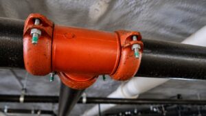


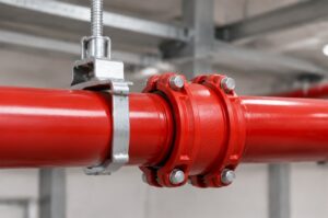
Mechanical tee hole spacing involves more than leaving metal between two openings. The selected fitting also needs an acceptable sealing area and enough room for its housing, bolts and branch connection. There is no universal spacing value to infer from outlet size alone. Before drilling, establish the required hole location against the exact fitting instructions and the surrounding pipe features. A branch center marked on a layout drawing is the beginning of that check.
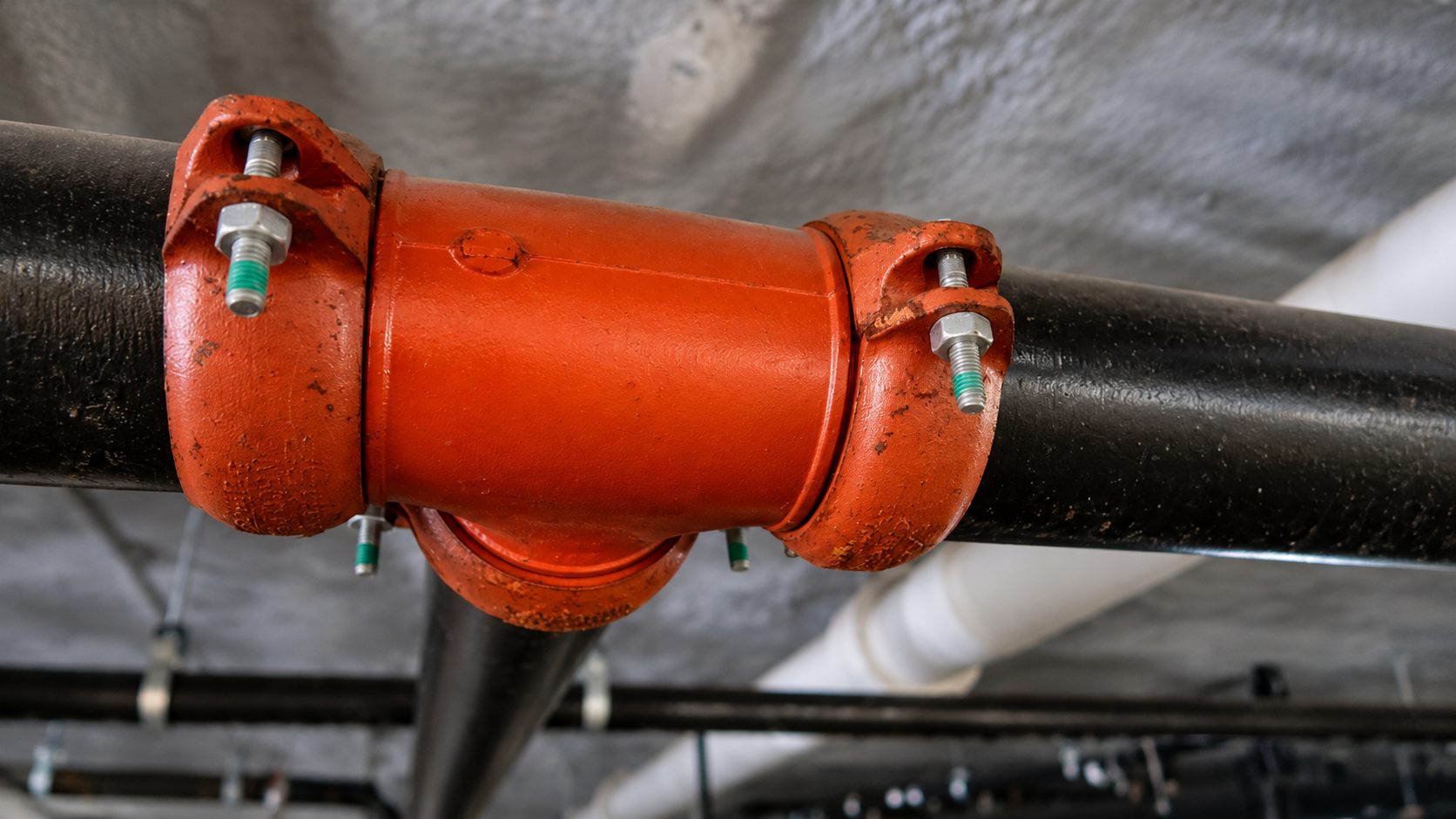
Locate the Branch from a Defined Pipe Reference
A measurement is useful only when its endpoints are clear. Put the pipe end or another fixed reference on the drawing before dimensioning the branch center.
Hole Centers and Edge Distances
The XGQT15S threaded mechanical tee is an identifiable fitting to use in that review. Record its run and outlet sizes separately, together with the actual run pipe outside diameter. Its general size range does not provide the preparation dimensions for every combination.
Center spacing is measured between hole centers. Edge distance describes the space from a hole boundary to another boundary or feature. They are different measurements. For two circular holes on the same longitudinal line, the clear axial distance between their edges equals the center spacing minus both hole radii.
For illustration only, assume two holes have diameters of 50 mm and 40 mm, with centers 250 mm apart. Their clear axial edge distance would be 205 mm. These hypothetical numbers are neither XGQT15S dimensions nor permitted minimums. The calculation simply prevents a center measurement from being reported as an edge measurement. It says nothing about the clearance needed by the surrounding fittings.
Reserve the Sealing Area Around Each Opening
After locating the hole edges, consider the pipe surface that each gasket and housing needs. A hole may miss an obstruction while the fitting around it still overlaps that obstruction.
Grooves and Weld Features
On a branch near a pipe end, show the end preparation and adjacent coupling as well as the new opening. Compare their positions with the mechanical tee’s required preparation and seating areas. A dimension to the cut end alone does not reveal whether the tee will sit across a groove or foul the coupling housing.
Identify weld seams, raised features and local surface defects near the proposed position. Their relationship to the hole and seal needs review under the applicable product instructions. Do not grind a seam or remove pipe wall simply to obtain an apparently smooth gasket seat. Where a location is unsuitable, a revised branch position or engineered alternative is preferable to an unapproved alteration.
VICAST’s mechanical tee hole diameter guidance explains the separate choice of hole size. Use that information alongside the position review. Selecting the correct saw does not establish where it is acceptable to drill.
Adjacent Branch Openings
With two outlets on the same run, draw both fitting envelopes around their holes. Check the pipe condition beneath each gasket and the space occupied by both housings. A visible strip of metal between holes cannot establish that either seal has the surface it needs.
The review also needs any manufacturer or project restriction on adjacent openings. If the available documents give no minimum separation for the proposed arrangement, request confirmation with a dimensioned sketch. Neither a positive edge distance nor a successful trial fit supplies the missing requirement.
Check the Housing and Branch Assembly Space
A location that satisfies the preparation requirements still has to work during assembly. The complete fitting occupies space around the circumference, beyond the outline of the outlet itself.
Clearance Around the Run Pipe
Show the lower housing, bolt ends and nearby supports in a section. A main pipe close to a wall may leave the hole accessible while blocking installation of the rest of the tee. Include the approach needed by the specified tools. Drilling first and discovering this obstruction afterwards leaves an opening without an approved connection.
The mechanical tee range includes different arrangements. A drawing for a U-bolt style should not be used to establish the space required by XGQT15S. Keep the proposed model attached to its own dimensions throughout the layout review.
Threaded Branch Assembly
For a threaded outlet, account for the adjoining nipple, valve or other component and its assembly method. The branch might fit in its final position yet lack room to be installed. Confirm the thread specification and how the mating component will be assembled without forcing the tee out of its intended position.
Rotating the proposed branch around the run can change access, but it also changes the branch route. Any such revision needs to be coordinated with the drawing before the hole position is released.
Resolve Conflicts Before Drilling
When an outlet conflicts with a groove, another fitting or the available working space, mark the affected dimensions for the designer and supplier. A useful sketch shows the hole center and diameter, pipe end, nearby features and complete fitting envelope. Ask which location or connection arrangement is acceptable.
Keep an unsuitable marked position out of the cutting instructions. If the pipe has already been drilled, stop and obtain an approved disposition rather than elongating the hole to shift the outlet. Work on existing piping requires the site’s isolation, depressurization and drainage procedure before cutting or adjustment.
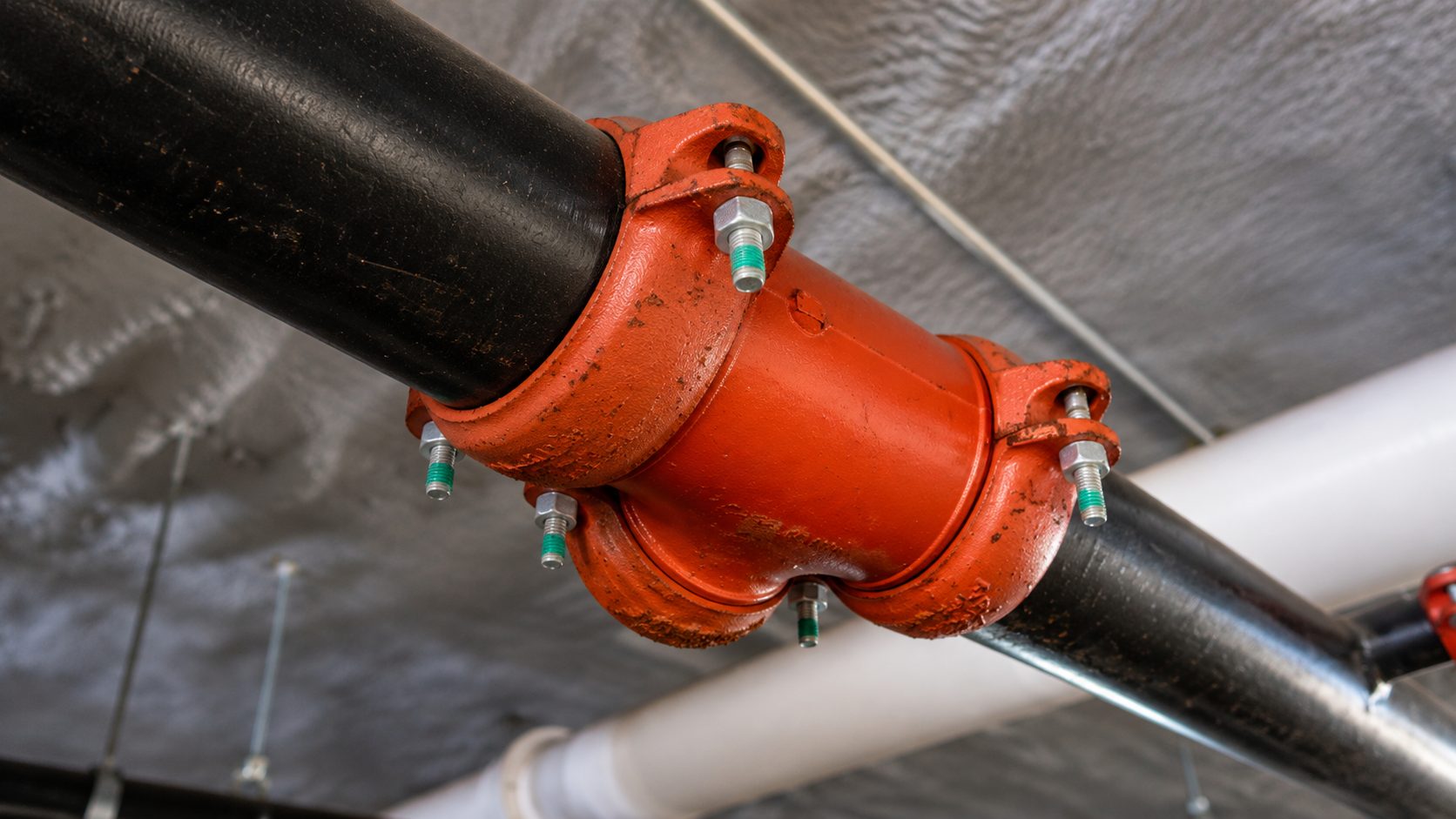
Confirm XGQT15S Layout Data with VICAST
VICAST publishes XGQT15S product information, including a general size range of 1 to 10 inches, or DN25 to DN250, and a data-list download entry. Buyers can use that reference when requesting the dimensions for the proposed run and outlet combination.
Send the sizes and a simple location sketch with the quotation inquiry. Request the applicable hole preparation and housing dimensions, highlighting any adjacent groove, weld or outlet. Any spacing requirement still unanswered belongs in that technical discussion before the pipe is drilled.
Conclusion
Establish mechanical tee hole spacing from defined reference points, then check the required sealing area and the complete assembly. Resolve missing separation requirements with the selected product’s supplier and project designer. The released hole position should leave room for an approved connection, not merely an opening of the correct diameter.
FAQs
Does a larger main pipe automatically allow closer branches
No. Its diameter does not establish the required separation or seating area for the selected fittings. Review the actual arrangement.
Can a mechanical tee cover an unused hole beside the new outlet
Do not use the housing as an improvised repair. An unused opening needs an approved disposition before the revised branch arrangement proceeds.
Does rotating one outlet solve insufficient axial spacing
Rotation changes the circumferential position, but does not establish acceptable separation. The revised openings, sealing areas and housings still need review together.
mechanical tee hole spacing(主关键词)
mechanical tee hole location
threaded mechanical tee
mechanical tee installation clearance
XGQT15S mechanical tee