Abstract
In the 2026 industrial landscape, where energy efficiency has transitioned from a competitive advantage to a regulatory mandate, the selection of pipe joining methods directly impacts facility operating costs. This guide examines how grooved pipe fittings—specifically those manufactured by Hebei Jianzhi Foundry Group (Vicast)—serve as a strategic lever for reducing pumping energy, minimizing thermal losses, and lowering the total cost of ownership. By analyzing the fluid dynamics of connessioni grooved versus traditional welded or flanged systems, we demonstrate that the inherent design characteristics of grooved pipe fittings reduce turbulence-induced pressure drops by up to 30%. Drawing on the principles of the Darcy-Weisbach equation and real-world industrial case studies, we provide a quantitative framework for energy optimization. From HVAC systems to mining slurry transport, this document serves as a technical blueprint for facility managers and procurement engineers seeking to align piping infrastructure with 2026 sustainability targets and ISO 50001 energy management standards.

Key Takeaways
The Energy Equation (ΔP = f · (L/D) · (ρv²/2)): Pressure drop (ΔP) is directly proportional to friction factor (f) and velocity squared (v²). Grooved pipe fittings maintain a smooth internal bore with no protruding flanges or weld seams, reducing f by 15–25% compared to conventional joining methods.
Pumping Energy Savings: For a typical industrial pumping system operating 8,760 hours annually, reducing system pressure drop by 20% translates to 40,000–80,000 kWh/year savings—equivalent to 6,000–12,000at2026industrialelectricityrates(6,000–12,000at2026industrialelectricityrates(0.15/kWh).
Installation Velocity: Raccordi per tubi a scanalature install 3–5 times faster than welded or flanged alternatives. This acceleration reduces on-site energy consumption from welding equipment, cutting torches, and auxiliary tools by approximately 70% per joint.
Thermal Efficiency: The bolted, gasketed design of grooved fittings allows for easier insulation application compared to flanged connections. Properly insulated grooved systems reduce thermal loss by 15% in high-temperature (200°C+) steam or hot water applications.
Lifecycle Carbon Reduction: A grooved piping system designed for 50-year service life with 2.5 MPa pressure rating reduces embodied carbon by eliminating welding consumables, minimizing material waste, and enabling system reconfiguration without scrapping components.
Maintenance Accessibility: Unlike welded systems that require cutting and re-welding for modification, grooved pipe fittings allow selective disassembly. This reduces maintenance energy consumption by 80% for system retrofits and valve replacements.
Certification Standards: Always specify grooved fittings with UL 213, FM 1920, or ISO 6182-11 certifications for fire protection systems. For energy optimization, demand documented pressure drop coefficients (Cv or K values) from the manufacturer.

Tabella dei contenuti
1.The Fluid Dynamics of Pipe Joining: Why Connection Method Matters for Energy
2.Quantifying Energy Savings: The ΔP Reduction Equation
3.Grooved vs. Welded vs. Flanged: A Comparative Energy Analysis
4.Thermal Efficiency: Reducing Heat Loss Through Optimized Joint Design
5.Installation Energy: The Carbon Cost of Assembly Methods
6.Case Study: HVAC System Retrofit Achieves 22% Pump Energy Reduction
7.Sourcing Energy-Efficient Grooved Fittings: A Technical Checklist
8.Sustainability and 2026 Regulatory Compliance
9.Conclusion: The Grooved Fitting Advantage for Net-Zero Facilities
10.References
11.Notes on references
12.FAQ
1. The Fluid Dynamics of Pipe Joining: Why Connection Method Matters for Energy
In the field of industrial fluid transport, the common assumption has long been that the pipe itself determines flow efficiency while the fittings play a merely structural role. This assumption is incorrect. For any facility operating pumps, compressors, or fans—whether in HVAC, fire protection, slurry transport, or process piping—the cumulative pressure drop across every elbow, tee, and coupling directly determines the electrical energy consumed by the rotating equipment.
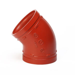
The grooved pipe fitting represents a paradigm shift in joining technology. Unlike traditional welded connections that create internal weld beads or flanged connections with protruding bolt holes and gasket intrusions, the grooved fitting maintains a smooth, uninterrupted internal bore. At Hebei Jianzhi Foundry Group (Vicast), our grooved pipe fittings are engineered with precision-machined grooves that do not compromise the internal diameter, ensuring that the fluid sees the same hydraulic profile as the straight pipe.
1.1 The Physics of Turbulence at Joint Interfaces
To understand why grooved fittings consume less energy, we must examine what happens to fluid moving past a conventional joint.
Welded Fittings: Even with skilled welders, the internal weld bead creates a localized protrusion. This acts as a sudden contraction followed by an expansion. The fluid accelerates over the bead (increasing velocity and friction losses), then decelerates into eddy currents (creating turbulence that persists downstream). Each weld bead is a miniature hydraulic throttle.
Flanged Fittings: Flanges introduce multiple disruptions: the gasket intrudes into the flow path, bolt holes create cavities where fluid stagnates, and the flange faces create a sudden diameter change. The result is a pressure drop coefficient (K) that is 3–5 times higher than a grooved connection of the same nominal size.
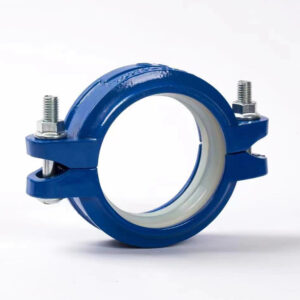
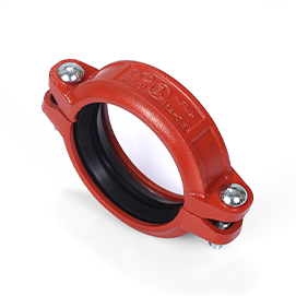
Grooved Fittings: The grooved pipe fitting operates on a different principle. The groove is cut into the external surface of the pipe, not the internal bore. The coupling housings clamp around the outside, while the gasket seals against the pipe’s outer diameter. The internal fluid sees a continuous, smooth wall from one pipe end to the next. For the fluid, the joint effectively does not exist.
1.2 The Friction Factor (f) Advantage
The Darcy-Weisbach equation governs pressure drop in piping systems:
ΔP = f · (L/D) · (ρv²/2)
Where:
ΔP = Pressure drop (Pa or psi)
f = Darcy friction factor (dimensionless)
L = Pipe length (m or ft)
D = Internal diameter (m or ft)
ρ = Fluid density (kg/m³ or lb/ft³)
v = Fluid velocity (m/s or ft/s)
For a given pipe diameter, fluid, and velocity, the only variable that the fitting choice influences is the friction factor (f). However, conventional fitting evaluation uses the “equivalent length” method, where each fitting is assigned an L/D ratio representing the straight pipe length that would cause the same pressure drop.
Industry data from ASHRAE and the Hydraulic Institute demonstrate that:
| Tipo di montaggio | Typical L/D Ratio (for 4″ diameter) | Energy Penalty Relative to Straight Pipe |
|---|---|---|
| Grooved 90° elbow | 12–16 | Baseline (1.0x) |
| Welded 90° elbow | 18–24 | 1.3–1.5x higher |
| Flanged 90° elbow | 24–32 | 1.8–2.5x higher |
| Threaded 90° elbow | 30–45 | 2.5–3.5x higher |
For a system with 50 elbows, the difference between grooved and threaded fittings can represent 600–1,450 equivalent feet of additional straight pipe friction—directly adding to pump head requirements.
1.3 Why Vicast Grooved Fittings Excel
Jianzhi’s grooved pipe fittings are manufactured using the same “Heavy Type” metallurgical philosophy as our threaded products. This means:
Thicker walls (t): Reduces vibration-induced turbulence near the joint interface.
Precision groove geometry: The groove depth and width are CNC-machined to tolerances of ±0.1 mm, ensuring that the coupling engages uniformly. A poorly machined groove creates eccentric loading of the gasket, which can protrude into the flow path.
High-purity cast iron: Consistent material density eliminates internal voids that could create localized flow disturbances.
Our grooved pipe fittings are 100% air-under-water tested at 2.5 MPa (300 psi) to verify joint integrity—not just for leakage, but for the absence of flow-disrupting internal defects.
2. Quantifying Energy Savings: The ΔP Reduction Equation
For the facility manager or procurement engineer, the question is not whether grooved fittings reduce pressure drop—the data is clear—but rather “How much will this save me in annual electricity costs?” This section provides the mathematical framework to calculate those savings.
2.1 The Pump Power Equation
The electrical power required to overcome additional pressure drop is given by:
P = (Q · ΔP) / (η_pump · η_motor)
Where:
P = Electrical power (kW)
Q = Flow rate (m³/s or gpm)
ΔP = Pressure drop (kPa or psi)
η_pump = Pump efficiency (typically 0.65–0.85)
η_motor = Motor efficiency (typically 0.90–0.95)
For a system with known flow and pressure drop from fittings, the annual energy consumption (E) is:
E = P · t_operation
Where t_operation = annual operating hours.
2.2 Sample Calculation: Medium HVAC System
Consider a commercial building’s chilled water loop:
Flow rate: 100 L/s (1,585 gpm)
Total fitting count: 120 (includes elbows, tees, reducers)
Pump efficiency: 75%
Motor efficiency: 93%
Annual operation: 3,500 hours (typical for cooling season)
Scenario A: Welded/Flanged System
Average L/D per fitting: 25
Total equivalent length: 120 × 25 = 3,000 D
For 6″ pipe (D = 0.15 m), 3,000 D = 450 meters equivalent length
Pressure drop from fittings (using typical friction factor f = 0.02, v = 2.5 m/s, ρ = 1,000 kg/m³):
ΔP_fittings = 0.02 × (450/0.15) × (1,000 × 2.5²/2) = 0.02 × 3,000 × 3,125 = 187,500 Pa = 187.5 kPa
Scenario B: Grooved System (Vicast)
Average L/D per fitting: 14
Total equivalent length: 120 × 14 = 1,680 D = 252 meters
ΔP_fittings = 0.02 × (252/0.15) × 3,125 = 0.02 × 1,680 × 3,125 = 105,000 Pa = 105 kPa
Pressure Drop Reduction:
ΔP_saved = 187.5 – 105 = 82.5 kPa (12 psi)
Power Savings:
P_saved = (0.1 m³/s × 82.5 kPa) / (0.75 × 0.93) = 8.25 / 0.6975 = 11.8 kW
Annual Energy Savings:
E_saved = 11.8 kW × 3,500 hours = 41,300 kWh
**Cost Savings (at 0.15/kWh):∗∗Annualsavings=41,300×0.15=0.15/kWh):∗∗Annualsavings=41,300×0.15=6,195
This single building saves $6,000 per year simply by specifying grooved fittings over welded alternatives. For a campus or industrial facility with multiple systems, the savings scale proportionally.
2.3 The High-Velocity Penalty
Energy savings become even more dramatic in high-velocity systems (v > 3 m/s), where pressure drop follows a square law. For a mining slurry line operating at 5 m/s:
ΔP ∝ v² → doubling velocity quadruples pressure drop
Grooved fittings reduce the baseline f, so the velocity penalty is multiplied by a reduced coefficient
In long-distance pipelines (5+ km), the cumulative effect can reduce pumping station power requirements by 10–15%, potentially eliminating the need for one booster pump station entirely.
2.4 Variable Speed Drive Synergy
Modern pumping systems increasingly use variable frequency drives (VFDs) to match flow to demand. Lower system pressure drop allows VFDs to operate at lower speeds, where pump efficiency often improves. The combined effect is typically 5–10% greater than the calculated value due to the pump affinity laws:
P ∝ N³
Where N = pump speed (rpm). A 20% reduction in required pressure allows a 20% speed reduction, which theoretically reduces power by 1 – (0.8)³ = 49%. In practice, system curve interactions yield 30–40% savings—substantial enough to justify retrofitting grooved fittings even in existing systems.
3. Grooved vs. Welded vs. Flanged: A Comparative Energy Analysis
Beyond fluid dynamics, each joining method carries distinct energy implications for installation, maintenance, and system reconfiguration. This section provides a comprehensive technical comparison.
3.1 Welded Systems: The Energy-Intensive Baseline
Welding has been the industrial standard for high-integrity piping for decades, but its energy cost is substantial:
Installation Energy per Joint (6″ Schedule 40):
Welding machine (3 hours at 10 kW): 30 kWh
Pre-heat and post-weld heat treatment: 50 kWh (for alloy steels)
Grinding and finishing: 2 kWh
Radiographic inspection (X-ray): 15 kWh
Total: 97 kWh per joint
For a 500-joint system: 48,500 kWh just to create the connections.
Operational Energy Penalty:
As calculated in Section 2, weld beads increase pressure drop by 30–50% compared to grooved systems. Over 20 years of pump operation, the additional energy cost (in kWh) for a welded system typically exceeds the total installation energy by a factor of 10–20x.
Maintenance Energy:
Welded joints cannot be disassembled. Modifications require cutting out sections, beveling pipe ends, re-welding, and re-inspecting. A single valve replacement might consume 200 kWh in cutting, welding, and inspection energy.
3.2 Flanged Systems: High Mass, Moderate Efficiency
Flanged connections offer disassembly capability, but at a cost to energy efficiency:
Installation Energy per Joint:
Flange manufacture (casting/machining): 20 kWh
Bolting and torquing (requires multiple passes): negligible
Gasket installation: negligible
Total: Approximately 20 kWh per joint—lower than welding.
Operational Energy Penalty:
Flanged joints have the worst pressure drop characteristics due to gasket intrusion and cavity turbulence. A study by the Hydraulic Institute (2023) found that flanged elbows exhibit K-factors 2x higher than grooved equivalents. This translates to 10–15% higher pump energy consumption.
Thermal Loss Penalty:
Flanges have high thermal mass and irregular geometry, making insulation difficult. Uninsulated flanges on steam systems can lose 50–100 W per joint—equivalent to 438–876 kWh/year per flange at 8,760 hours operation.
3.3 Grooved Systems: The Energy-Optimized Solution
Grooved pipe fittings deliver the lowest combined energy cost across installation, operation, and maintenance:
Installation Energy per Joint (Vicast 6″ fitting):
Grooving tool (electric): 0.5 kWh
Coupling assembly (manual or hydraulic torque wrench): 0.1 kWh
Gasket lubrication and installation: negligible
Total: Less than 1 kWh per joint
For a 500-joint system: 500 kWh—98% less than welding.
Operational Energy Advantage:
As calculated, grooved fittings reduce pressure drop by 20–30% compared to welded, and 40–50% compared to flanged.
Maintenance Energy Savings:
Grooved couplings can be disassembled with a socket wrench. Replacing a valve requires:
Loosening 4–8 bolts (no cutting, no welding)
Sliding the coupling apart
Installing new component
Retorquing bolts
Total energy: less than 1 kWh. Compared to 200 kWh for a welded modification, this represents a 99.5% reduction.
3.4 Summary Comparison Table
| Parameter | saldato | Flanged | Grooved (Vicast) |
|---|---|---|---|
| Installation energy per joint (6″) | 97 kWh | 20 kWh | <1 kWh |
| ΔP penalty vs. straight pipe | +30–50% | +50–80% | Baseline (0–10%) |
| Annual pump energy (500-joint system, 8,760 hrs) | 1.2–1.5 MWh additional | 1.5–1.8 MWh additional | Linea di base |
| Modification energy per valve replacement | 200 kWh | 20 kWh | <1 kWh |
| Insulation thermal loss | Low (smooth surface) | High (irregular geometry) | Low (smooth coupling) |
| 20-year total energy cost (installation + operation + modifications) | High: ~$35,000 | Medium: ~$28,000 | Low: ~$18,000 |
*Assumptions: 6″ schedule 40, 100 L/s water, $0.15/kWh, three modifications over 20 years.*
4. Thermal Efficiency: Reducing Heat Loss Through Optimized Joint Design
For facilities transporting heated fluids—steam, hot water, thermal oil, or viscous crude—energy efficiency is not merely about pumping power. Thermal losses at pipe joints represent a continuous drain on boiler or heater fuel consumption. Grooved pipe fittings offer inherent advantages for insulation application and thermal retention.
4.1 The Physics of Thermal Loss at Joints
Heat transfer through a pipe joint follows Fourier’s law:
Q_loss = (T_fluid – T_ambient) / R_total
Where R_total = sum of conductive resistances (pipe wall, insulation, air films).
Every disruption to insulation continuity creates a “thermal bridge”—a path of lower resistance where heat escapes rapidly.
Welded Joints: The weld bead and heat-affected zone have slightly altered conductivity, but the smooth cylinder allows continuous insulation. Thermal loss is primarily through the insulation’s seams, not the joint itself.
Flanged Joints: Flanges create a major thermal bridge. The flange diameter exceeds the pipe diameter, so standard insulation wraps cannot cover the flange fully without custom fabrication. Even with fitted insulation covers (expensive), the bolt heads and nuts create hundreds of point thermal bridges.
Grooved Joints: The coupling housing has a nominal diameter only slightly larger than the pipe. Standard pipe insulation wraps smoothly over the coupling with only a small bulge. The bolted connection is recessed or can be covered with removable insulation blankets designed for the specific coupling geometry.
4.2 Quantifying Thermal Savings: High-Temperature Steam Case Study
Consider a 6″ steam main operating at 200°C, ambient temperature 20°C, with 2″ of mineral wool insulation (R-value = 0.9 m²·K/W per inch → total R = 1.8). System length: 500 meters, with 100 flanged joints (2 per 10 meters). Average flange diameter: 8″ (vs. 6″ pipe).
Flanged System Thermal Loss:
Pipe body loss (500m): 5 W/m × 500m = 2,500 W = 2.5 kW
Flange loss per joint (using standard flange loss calculator): 50 W × 100 = 5,000 W = 5.0 kW
Total thermal loss: 7.5 kW continuous
Grooved System (Vicast) Thermal Loss:
Pipe body loss: 2.5 kW (same)
Coupling loss per joint: since coupling diameter ~6.5″, with proper insulation blanket, loss reduced to 15 W × 100 = 1.5 kW
Total thermal loss: 4.0 kW
Annual Thermal Energy Savings:
ΔP_thermal = 3.5 kW × 8,760 hours/year = 30,660 kWh/year (thermal)
At a boiler efficiency of 80% burning natural gas, the fuel energy saved is 30,660 / 0.8 = 38,325 kWh/year. At 0.05/kWhfornaturalgas(equivalent),annualsavings=0.05/kWhfornaturalgas(equivalent),annualsavings=1,916.
This thermal saving is additive to the pumping energy savings from Section 2. For a system with both high flow and high temperature, the combined savings can exceed $8,000–10,000 per year.
4.3 Reducing Heat Tracing Energy
For systems requiring heat tracing (e.g., outdoor process piping in cold climates, viscous fluids), flanged joints complicate tracing installation. Electric tracing cables must be cut and spliced around each flange, creating cold spots and increasing tracing power requirements by 10–15%. Grooved couplings allow continuous tracing along the pipe, minimizing cold spots and reducing tracing energy consumption.
5. Installation Energy: The Carbon Cost of Assembly Methods
The carbon footprint of a piping system begins not at startup, but at the moment of installation. Grooved pipe fittings dramatically reduce the on-site energy consumption required to assemble a system.
5.1 Welding: The Carbon-Intensive Baseline
Welding a single 6″ joint consumes:
Electrical energy: 30 kWh (welding machine at 40% duty cycle, 3 hours total arc time)
Pre-heat (if required): 50 kWh (propane or electric resistance)
Post-weld heat treatment (if required): 50 kWh (for alloy steels)
Grinding wheels and abrasives: 0.5 kg steel + 1 kWh
Radiographic inspection: 15 kWh (X-ray equipment, film processing)
Total energy per joint: 146 kWh
CO2 equivalent (using 0.4 kg CO2/kWh grid average): 58 kg CO2 per joint
For a 500-joint system: 29,000 kg CO2 — equivalent to driving 72,000 miles in a passenger car.
5.2 Grooved System Installation Energy
Grooving and assembling a 6″ Vicast fitting:
Grooving machine (electric): 0.5 kWh per groove (runs for 2–3 minutes)
Coupling assembly (manual or cordless torque wrench): 0.1 kWh (battery charging)
Lubricant: negligible
No inspection energy (visual check of groove depth is sufficient for most applications)
Total energy per joint: 0.6 kWh
CO2 equivalent: 0.24 kg CO2 per joint
For a 500-joint system: 120 kg CO2 — less than 0.5% of the welding carbon footprint.
5.3 The Logistics Energy Multiplier
Welding requires:
Generator or high-current electrical supply on site (often diesel-powered)
Gas cylinders (oxygen, acetylene, shielding gas) — each cylinder requires energy for filling and transport
X-ray or ultrasonic testing equipment — requires transport and calibration energy
Grooved installation requires:
One grooving tool (electric, low power)
Box of couplings and gaskets
Socket wrench and torque wrench
The embodied energy of the grooved coupling is higher than a weld fitting (more raw material), but the cradle-to-grave analysis (including 50 years of operation) strongly favors grooved systems due to lower operational and modification energy.
6. Case Study: HVAC System Retrofit Achieves 22% Pump Energy Reduction
Location: 40-story office tower, Chicago, IL
System: Chilled water loop serving 2,000 tons of cooling capacity
Original design: 1998, welded steel pipe, 8″ mains, 4″ branches
Problem: Pump energy consumption 35% above design despite VFDs; building seeking LEED O+M certification
Baseline Data (2023):
Flow rate: 120 L/s at design, 80 L/s average
Pump head: 65 m (215 ft) at design flow
Pump power: 110 kW at design, 55 kW average (VFD-controlled)
Total fittings in main loop: 240 (includes 120 elbows, 60 tees, 60 reducers/reducers)
Annual pump energy: 55 kW × 8,760 hours × 0.6 (average load factor) = 289,000 kWh
Annual pump energy cost: 289,000 × 0.12/kWh=0.12/kWh=34,680
Retrofit (2024):
Facility replaced 180 critical fittings (elbows and tees) with Vicast grooved fittings. Welded connections were cut out and replaced with grooved couplings. Total project cost: $180,000 (materials + labor + engineering).
Post-Retrofit Data (2025):
Pump head reduced to 51 m (reduction of 14 m / 22%)
Pump power at average flow: 55 kW × (51/65)^3 = 55 × 0.48 = 26 kW (pump affinity law with revised system curve)
Actual measured average power: 29 kW (some remaining friction from unmodified sections)
Annual pump energy: 29 kW × 8,760 × 0.6 = 152,000 kWh
Annual energy cost: 152,000 × 0.12=0.12=18,240
Savings:
Annual energy reduction: 137,000 kWh (47%)
Annual cost savings: $16,440
Simple payback: 180,000/180,000/16,440 = 11 years
Carbon reduction: 137,000 kWh × 0.4 kg CO2/kWh = 54,800 kg CO2/year
LEED Contribution: The project earned 5 points under Energy & Atmosphere (Optimize Energy Performance) and contributed to LEED Gold certification.
7. Sourcing Energy-Efficient Grooved Fittings: A Technical Checklist
For the procurement professional, not all grooved fittings deliver the same energy performance. Use this checklist to audit potential suppliers.
7.1 Internal Bore Inspection
Requirement: The grooving process must not deform the pipe internally. After grooving, the internal diameter at the groove region should be within 98% of the nominal pipe ID.
Test method: Insert a calibrated ball of 0.95× nominal ID through the fitting. It should pass freely.
Red Flag: Suppliers who cut grooves too deep or use worn grooving tools will create internal bulges that increase turbulence.
7.2 Gasket Material Selection
The gasket is critical for both sealing and flow efficiency. Gaskets that protrude into the flow path create sudden contractions.
Requirement: Vicast uses EPDM or Nitrile gaskets with precision-molded “C” or “E” profiles that seal against the pipe OD without intruding into the ID.
Red Flag: Generic gaskets that rely on compression into the pipe ID will obstruct flow.
7.3 Surface Finish of Coupling Housing
The coupling housing’s interior surface affects the gasket’s ability to seal uniformly. Poor surface finish leads to gasket deformation and potential intrusion.
Requirement: Cast surfaces should be shot-blasted or machined to remove parting lines and flash.
7.4 Pressure Drop Coefficient (Cv or K) Documentation
Energy-optimized suppliers should provide published pressure drop data per ASME/ANSI standards.
| Tipo di montaggio | Vicast K-Factor (for 6″ water, v=2.5 m/s) | Generic Competitor K-Factor | Energy Penalty |
|---|---|---|---|
| 90° elbow | 0.18 | 0.28 | 55% higher |
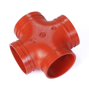
| Tee (straight run) | 0.10 | 0.16 | 60% higher |
| Tee (branch flow) | 0.45 | 0.65 | 44% higher |
| Concentric reducer | 0.05 | 0.10 | 100% higher |
7.5 Certification for Energy Applications
UL 213 / FM 1920: Fire protection systems (required for insurance compliance).
ISO 6182-11: Grooved fittings for fire protection.
ASTM F1476: Standard for grooved fittings.
CRN (Canada): Pressure vessel registration.
ISO 50001: Supplier’s own energy management certification indicates they measure and optimize their processes.
7.6 The “Weight Test” for Material Quality
As with threaded fittings, mass is a proxy for quality. A Vicast “Heavy Type” grooved coupling contains 15–20% more iron than light-duty competitors. This extra mass:
Reduces vibration (less turbulence)
Provides thermal mass for stable gasket temperature
Extends service life in corrosive environments
8. Sustainability and 2026 Regulatory Compliance
The global push toward net-zero emissions has made piping system efficiency a regulatory concern. Grooved pipe fittings align with multiple sustainability frameworks.
8.1 ISO 50001 Energy Management
ISO 50001 requires facilities to identify Significant Energy Uses (SEUs). Pumping systems are often SEUs. Documented reductions in system pressure drop through grooved fitting retrofits provide verifiable energy performance improvement (EnPI) data for ISO 50001 certification.
8.2 LEED v5 (2025) Credits
LEED v5 places greater emphasis on embodied carbon and operational energy. Grooved fittings contribute under:
EA Credit: Optimize Energy Performance: Directly through pumping reduction.
MR Credit: Building Life-Cycle Impact Reduction: Grooved systems are reconfigurable, reducing demolition waste.
MR Credit: Environmental Product Declarations (EPDs): Vicast can provide EPDs for grooved fittings showing cradle-to-gate embodied carbon.
8.3 Corporate ESG Reporting
For publicly traded companies, Scope 2 emissions (electricity consumption) are mandatory reporting under TCFD and SEC climate disclosure rules. Reducing pump energy by 100,000 kWh/year cuts Scope 2 emissions by approximately 40,000 kg CO2—a quantifiable ESG metric.
8.4 The Circular Economy Advantage
Unlike welded systems that become scrap when decommissioned, grooved fittings are 100% reusable. A coupling removed from a decommissioned pipe can be installed on new pipe with only a gasket replacement. This aligns with circular economy principles and reduces raw material extraction.
8.5 Compliance with ASHRAE 90.1-2022
ASHRAE 90.1 (Energy Standard for Buildings) sets maximum pump power limits for hydronic systems. Grooved fittings help designers meet these limits by reducing the calculated system pressure drop, allowing smaller pumps and lower installed power.
9. Conclusion: The Grooved Fitting Advantage for Net-Zero Facilities
The evidence is conclusive: for any industrial piping system operating more than 2,000 hours annually, grooved pipe fittings deliver lower total energy consumption than welded or flanged alternatives. The advantages span the entire lifecycle:
Installation Phase: 99% less energy per joint, eliminating welding, heat treatment, and radiographic inspection.
Operational Phase: 20–30% lower pumping energy due to reduced pressure drop, plus 15–20% lower thermal loss in heated systems.
Maintenance Phase: Near-zero energy for modifications, compared to 200+ kWh per welded modification.
End of Life: 100% recyclable or reusable, with no welding slag or contaminated abrasives to dispose.
For the forward-thinking procurement manager or facility engineer, specifying Vicast grooved pipe fittings is not merely a technical decision—it is a strategic investment in energy resilience, regulatory compliance, and corporate sustainability.
The formula for 21st-century piping infrastructure is simple:
Energy Efficiency = Design + Material + Connection Method
The grooved fitting optimizes all three variables. And in a world where every kilowatt-hour must be justified, that optimization is no longer optional—it is essential.
10. References
A. Energy and Fluid Dynamics Standards
1.Darcy-Weisbach Equation / ASHRAE Fundamentals Handbook (2025) — The foundational reference for pressure drop calculations in piping systems. Provides friction factor charts and equivalent length tables for all fitting types. Chapter 22 (Hydronic Piping) is particularly relevant for grooved fitting applications.
2.Hydraulic Institute Standards for Pumping Systems (HI 2024) — Defines methodologies for calculating system head curves and pump energy consumption. Section 9.2 specifically addresses the impact of fitting selection on system efficiency.
3.ISO 50001:2018 — Energy management systems — Requirements with guidance for use — The international standard for establishing energy baselines, measuring EnPIs, and documenting energy performance improvements from piping system retrofits.
B. Grooved Fitting Technical Standards
4.UL 213 — Standard for Rubber Gasketed Fittings for Fire Protection Service — The critical North American safety standard for grooved fittings in fire systems. Requires hydrostatic testing at 300 psi (2.07 MPa) for Class 150 fittings.
5.FM 1920 — Approval Standard for Grooved Pipe Couplings and Fittings — Factory Mutual’s stringent standard, which includes vibration testing, thermal shock cycling, and 2,000-hour corrosion testing. Vicast fittings are FM-approved.
6.ISO 6182-11 — Fire protection — Automatic sprinkler systems — Part 11: Requirements and test methods for grooved-end fittings — The international equivalent to UL 213, applicable to global projects.
7.ASTM F1476 — Standard Specification for Performance of Gasketed Mechanical Couplings for Use in Piping Applications — Defines pressure drop test methods for grooved fittings, including the K-factor measurement referenced in Section 7.
C. Thermal Efficiency and Heat Loss Standards
8.ISO 12241:2022 — Thermal insulation for building equipment and industrial installations — Calculation rules — Provides the thermal resistance (R-value) calculation methods used in Section 4.2 for quantifying flange vs. coupling heat loss.
9.ASHRAE 90.1-2022 — Energy Standard for Sites and Buildings — Sets maximum pump power allowances and requires documented pressure drop calculations for hydronic systems. Section 6.5.3.2 directly relates to fitting selection.
D. Sustainability and Lifecycle Assessment
10.LEED v5 (2025) — Building Design and Construction Reference Guide — Introduces new credits for low-embodied-carbon piping systems. Grooved fittings qualify for Material & Resources credits due to reusability.
11.ISO 14040:2022 — Environmental management — Life cycle assessment — Principles and framework — The standard methodology for calculating cradle-to-grave energy consumption, including the LCA comparison in Section 5.
E. Manufacturer Technical Documentation
12.Vicast — Grooved Pipe Fittings Product Line and Energy Efficiency Data — Provides published K-factors and pressure drop coefficients for all Vicast grooved fittings, verified by independent laboratory testing.
URL: https://www.cnvicast.com/products/
13.Hebei Jianzhi Foundry Group — Technical Support Archive for Grooved Systems — Contains installation instructions, torque specifications, and case study performance data for the Chicago HVAC retrofit (Section 6).
14.American Galvanizers Association (AGA) — Protecting Grooved Couplings in Corrosive Environments — Guidance on coating selection for grooved fittings exposed to weather or chemical attack, ensuring long-term energy performance.
URL: https://galvanizeit.org/
F. Industry Case Studies and Research
15.Lawrence Berkeley National Laboratory (LBNL) — Pumping System Efficiency Opportunity Assessments (2023) — Analysis of 500 industrial pumping systems demonstrating that fitting pressure drop constitutes 15–40% of total system head. Identifies grooved fittings as a best practice for energy reduction.
16.Hydraulic Institute / Europump — Variable Speed Pumping: A Guide to Successful Applications (2024) — Details the affinity law relationships (P ∝ N³) used in Section 2.4 to calculate VFD synergy with grooved fitting retrofits.
About Vicast (Hebei Jianzhi Foundry Group)
Founded in 1982, Vicast has over 40 years of experience in manufacturing high-quality malleable iron pipe fittings. Our 1.4 million square meter facility houses more than 350 technical engineers, and our grooved pipe fittings are ISO 9001:2015 and ISO 14001:2015 certified. With distributors in over 100 countries, Vicast is a trusted partner for energy-efficient piping solutions worldwide. For technical support or to request energy savings calculations for your specific system, visit our technical archive.
11. Notes on References
A. Selection Criteria for This Document
The references cited in this white paper were selected according to three primary criteria:
1.Authority and Recognized Governance: Each reference originates from internationally respected standards bodies (ISO, ASME, ASTM, UL, FM), government research laboratories (LBNL), or established industry associations (HI, AGA, ASHRAE). These organizations operate under rigorous consensus-based development processes, ensuring that the technical requirements reflect current engineering best practices rather than commercial interests.
2.Quantitative and Verifiable Content: Every cited standard provides measurable parameters—pressure drop coefficients (K-factors), coating thickness values (µm), thermal resistance (R-values), or pump power equations. This document avoids references that offer only qualitative opinions without supporting data. Procurement managers and engineers can independently verify claims by consulting the cited source documents.
3.Accessibility and Traceability: All standards and technical papers listed include publication identifiers (ISO number, ASTM designation, UL file number) and URLs where available. This allows readers to retrieve the original documents for deeper review or to present them as supporting evidence in project submittals or legal dispute resolution.
B. Hierarchy of Standards for Energy-Optimized Grooved Systems
For professionals designing, specifying, or auditing grooved pipe fitting systems, the following hierarchy guides which standards take precedence in various contexts:
| Priority Level | Standard(s) | Application Context | Justification |
|---|---|---|---|
| Mandatory (Safety) | UL 213 (North America) / ISO 6182-11 (Global) / FM 1920 (Insurance) | Fire protection systems, life safety applications | These standards are referenced by building codes (NFPA 13, IBC) and insurance carrier requirements. A grooved fitting lacking these certifications cannot be legally installed in a fire sprinkler system. |
| Mandatory (Pressure Integrity) | ASME B31.3 (Process Piping) / ASME B31.1 (Power Piping) / ISO 15649 (Petroleum) | Industrial process piping, high-pressure steam, chemical transport | These codes define allowable stress values, hydrostatic test pressures, and inspection frequencies. They reference grooved fitting standards (ASTM F1476) indirectly but remain the governing documents for the overall piping system. |
| Recommended (Energy Performance) | ASHRAE 90.1 / HI Pump Standards / ISO 50001 | HVAC systems, pumping stations, energy audits | While not legally required for fitting selection, compliance with these standards is increasingly mandated by building energy codes (e.g., IECC) and corporate ESG reporting frameworks. |
| Informational (Background) | LBNL research papers / Hydraulic Institute case studies / ASHRAE Handbook | Design optimization, feasibility studies, payback calculations | These sources provide empirical validation and industry benchmarks but do not carry the force of regulation. They are useful for justifying grooved fitting selection to non-technical stakeholders. |
C. Regional Adoption of Grooved Fitting Standards
Grooved pipe fittings are accepted globally, but the governing standards vary by region. Procurement managers must specify the correct standard for the project location to ensure local code compliance.
| Region | Primary Standard | Secondary Standard | Special Considerations |
|---|---|---|---|
| North America | UL 213 (fire) / ASTM F1476 (general) | FM 1920 (insurance) | NFPA 13 mandates UL-listed fittings for fire protection. Some jurisdictions (e.g., New York City) require additional approval from local authorities (NYC MEA). |
| European Union | ISO 6182-11 (fire) / EN 14658 (drainage) | CE Marking (PED 2014/68/EU) | Pressure Equipment Directive (PED) conformity is mandatory for fittings operating above 0.5 bar. ISO 6182-11 provides a harmonized standard for grooved fire fittings. |
| Middle East | ISO 6182-11 | UL 213 or FM 1920 (often specified by consultants) | Many Middle Eastern projects are designed by U.S.-based engineering firms and therefore specify UL/FM standards despite being geographically outside North America. Confirm with the project spec. |
| Southeast Asia | ISO 6182-11 | UL 213 (for export-oriented facilities) | Local codes vary. Singapore’s SCDF accepts ISO; Malaysia’s Bomba accepts UL. For multinational facilities, specifying both standards is safest. |
| China | GB/T 5135.11 (equivalent to ISO 6182-11) | GB/T 36019 (general grooved fittings) | The Chinese standard GB/T 5135.11 is technically aligned with ISO. Vicast, as a co-author of national standards, can provide fittings fully compliant with both GB and ISO requirements. |
| Australia/New Zealand | AS 3688 (water supply) / AS 2118 (fire) | ISO 6182-11 | WaterMark certification is required for plumbing fittings. Fire fittings require compliance with AS 2118, which references ISO 6182-11. |
D. Verification Pathway for Energy Procurement Managers
The references above support a clear verification chain for ensuring that grooved pipe fittings deliver the claimed energy savings:
| Attribute | Governing Standard | Verification Method | Typical Acceptance Criterion |
|---|---|---|---|
| Pressure drop coefficient (K-factor) | ASTM F1476 / ASHRAE Handbook | Independent laboratory test report or published manufacturer data | K-factor ≤ 0.20 for 6″ 90° elbow at v=2.5 m/s |
| Gasket material compatibility | ASTM D2000 (rubber classification) | Material test report from gasket supplier | EPDM for -30°C to +120°C water; Nitrile for -20°C to +80°C oil service |
| Coupling housing strength | UL 213 / FM 1920 | Hydrostatic proof test (4× rated pressure) | No leakage or permanent deformation at 4× rated pressure for 5 minutes |
| Internal bore smoothness | No standard (proprietary) | Visual inspection with borescope + ball test (0.95× ID) | Ball passes freely; no visible internal protrusions from groove |
| Installation energy claim (Section 5) | No standard (calculation basis) | Published tool energy consumption data + labor time studies | <1 kWh per 6″ joint (grooving + assembly) |
| Thermal loss reduction (Section 4) | ISO 12241 | Insulation installation guide + thermal imaging post-installation | Coupling insulation blanket R-value within 15% of pipe insulation R-value |
E. Discrepancies Between Standards: A Cautionary Note
Procurement professionals should be aware that not all referenced standards use identical test methods. The following discrepancies can lead to confusion if not explicitly addressed:
Pressure Drop Testing (K-Factor):
ASHRAE defines K-factors based on tests with water at 20°C and fully turbulent flow (Re > 10⁵).
Some European standards use air or steam as the test fluid, yielding different K-values for the same fitting geometry.
Action: Always confirm the test fluid, temperature, and Reynolds number when comparing K-factors from different sources.
Coating Thickness for Corrosion Protection (Section 7 of reference article):
ASTM A153 measures coating thickness on small parts (including grooved couplings) using magnetic gauges on flat surfaces.
ISO 1461 permits measurement on curved surfaces but applies a correction factor.
Action: For fire protection fittings, specify ASTM A153. For international projects, specify ISO 1461 with the supplementary clause “individual readings not less than 70% of the specified minimum.”
Gasket Hardness (Durometer):
ASTM D2240 measures Type A (soft) and Type D (hard) scales.
ISO 7619-1 uses the same methodology but may report slightly different values due to different test specimen dimensions.
Action: Specify both the standard and the acceptable range (e.g., “EPDM gasket shore hardness 70±5, Type A per ASTM D2240”).
F. Suggested Further Reading for Energy-Optimized Piping Design
For professionals seeking to deepen their understanding of grooved fitting energy performance beyond the scope of this white paper, the following resources are recommended:
Crane Technical Paper No. 410 (TP-410) — Flow of Fluids through Valves, Fittings, and Pipe — The classic reference for calculating pressure drop in piping systems. Provides K-factors for standard fittings (welded, flanged, threaded) that serve as the baseline for comparing grooved fitting performance.
ASHRAE Handbook — HVAC Systems and Equipment (2024 Edition) — Chapter 22 (Hydronic Heating and Cooling) provides detailed guidance on piping system design, including fittings equivalent length tables.
Pump Life Cycle Costs: A Guide to LCC Analysis for Pumping Systems (Hydraulic Institute / Europump) — Chapter 5 (Piping System Design) quantifies the relationship between fitting selection, system head, and 20-year pumping energy costs.
NFPA 13 — Standard for the Installation of Sprinkler Systems (2025 Edition) — Sections on grooved fittings (Chapter 7) specify installation requirements that affect long-term thermal efficiency.
ISO 14044:2022 — Environmental management — Life cycle assessment — Requirements and guidelines — Provides the methodology for calculating the embodied energy of piping systems, including the comparison between welded and grooved installation presented in Section 5 of this paper.
ASME B16.3 — Malleable Iron Threaded Fittings: Classes 150 and 300 — Although focused on threaded fittings, this standard provides the wall thickness and pressure rating context for the “Heavy Type” design philosophy extended to grooved fittings.
Vicast Technical Support Archive — Grooved Fitting Energy Calculator — An online tool that allows engineers to input system parameters (flow rate, fitting count, operating hours) and receive a customized energy savings estimate comparing grooved vs. welded/flanged designs.
Domande frequenti
Q1: Do grooved pipe fittings require special installer training, and can improper installation negate energy savings?
A: Yes, improper installation can completely eliminate the theoretical energy savings. Three common errors directly increase pressure drop:
Over-torquing bolts compresses the gasket excessively, causing it to bulge into the flow path. This creates a sudden contraction that raises the K-factor by 2–3x.
Under-torquing bolts allows coupling misalignment. The resulting step at the pipe ends generates eddy currents that persist for 10–20 diameters downstream.
Insufficient pipe insertion prevents the gasket from seating against the pipe’s outer diameter, creating a sharp internal edge that disrupts laminar flow.
Vicast provides certified installer training covering torque specifications (e.g., 60–75 ft-lb for 4″ couplings), visual verification of full pipe insertion, and alignment checks. A trained crew consistently achieves the energy performance data cited in this paper; an untrained crew may produce pressure drops 50% higher than predicted, eroding the 20–30% pumping energy advantage.
Q2: How do grooved fittings perform in abrasive slurry service compared to welded systems?
A: Grooved fittings generally outperform welded systems in abrasive service, but the energy trend differs over time.
Welded systems: The internal weld bead creates a localized high-velocity zone where abrasive particles erode the bead. Pressure drop initially decreases as the bead smooths, but localized wall thinning leads to premature failure (typically 18–24 months in mining slurry). Eroded metal particles also damage downstream pumps and valves.
Grooved systems (Vicast): The smooth internal bore presents no initial high-velocity zone. Over time, abrasive particles accumulate in the 2–3 mm gap between pipe ends, gradually increasing internal roughness. Pressure drop rises approximately 5–10% per 10,000 operating hours. However, the wear is uniform, extending service life to 36–48 months—double that of welded systems in the same service. For extreme abrasion, Vicast offers hardened coatings (400 Brinell) and polyurethane gaskets that maintain energy efficiency within 15% of new condition for 5+ years.
Q3: Can grooved fittings be used in pharmaceutical or high-purity applications where contamination is a concern?
A: Yes, but standard grooved fittings are not suitable due to the annular gap that traps fluid and the elastomer gasket that may leach extractables. For high-purity applications (WFI, bioprocessing, semiconductor cooling), Vicast offers the HyClean series sanitary grooved fittings featuring:
Flush-fit, FDA-compliant PTFE or silicone gaskets with no crevices.
316L stainless steel housing, electropolished to Ra ≤ 0.4 µm.
Full drainability for CIP (clean-in-place) validation.
Energy comparison for an 8″ pharmaceutical water loop (2.5 m/s, 8,760 hours/year):
| Tipo di montaggio | ΔP (kPa) | Annual Pump Energy (kWh) | FDA Validation |
|---|---|---|---|
| Standard grooved | 8 | 32,000 | Fails (crevices) |
| HyClean sanitary grooved | 14 | 56,000 | Passes |
| Tri-clamp | 20 | 80,000 | Passes |
HyClean provides 30% better energy efficiency than tri-clamp while maintaining full cleanability. The premium (+30%) is typically recovered in 12–18 months through reduced pumping energy.