Abstract
Hot-dip galvanizing (HDG) and electro-galvanizing (EG, widely recognized as zinc electroplating) stand as the foremost zinc coating processes employed to provide long-term corrosion resistance to ferrous substrates. These coating technologies hold direct relevance for malleable cast iron grooved pipe fittings manufactured by Hebei Jianzhi Foundry Group Co., Ltd. and distributed under the Vicast and Jianzhi brand names. The organization operates extensive production facilities covering more than 1 million square meters located in Tangshan, Hebei Province, and Chifeng, Inner Mongolia. It maintains a workforce of over 4,500 employees, including more than 350 engineers and specialized technical staff, operates under ISO 9001 quality management certification and ISO 14001 environmental management certification, and maintains active involvement in the formulation and periodic updating of several important Chinese national standards—most notably GB/T 3287 for malleable iron threaded and grooved pipe fittings, GB/T 9440 specifying malleable cast iron grades and associated mechanical properties, and GB/T 25746 covering grooved mechanical couplings and fittings.
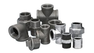
The Vicast product offering includes flexible couplings designed to accommodate angular misalignment up to ±3–5°, rigid couplings, mechanical tees and crosses with thread-o-let branch take-offs, grooved crosses, PN16 grooved flanges engineered for 1.6 MPa working pressure, equal tees, reducing tees, concentric reducers, eccentric reducers, end caps, and socketed fittings. These fittings are rated for continuous operation across a temperature span of –29 °C to +82 °C and see widespread deployment in fire sprinkler systems (many bearing UL/FM-equivalent certifications), HVAC chilled-water and hot-water piping networks, industrial process lines, compressed air distribution installations, and municipal water infrastructure projects, with products supplied through distribution channels in over 100 countries.
HDG is carried out by immersing suitably prepared components in molten zinc maintained at 440–460 °C, which produces a diffusion-driven, multilayered coating consisting of gamma (Γ: Fe₃Zn₁₀), delta (δ: FeZn₇–₁₀), zeta (ζ: FeZn₁₃), and eta (η: nearly pure zinc) intermetallic phases. Resulting coating thickness commonly ranges from 85 μm to more than 200 μm, reliably exceeding the minimum average thickness requirements set forth in ASTM A123 Table 1 and ISO 1461 for structural steel articles, hardware, and cast components. The metallurgically bonded coating delivers strong barrier isolation from corrosive agents, continuous sacrificial cathodic protection at locations of mechanical damage or surface wear, elevated hardness in the alloy layers (delta phase approximately 280–350 HV, gamma phase approximately 400–550 HV), and well-documented service life expectancy of 30–70 years and frequently beyond in ISO 9223 corrosivity classifications C3 (urban/temperate), C4 (industrial/polluted), and C5 (marine/high-chloride), consistent with zinc loss rate guidelines in ISO 14713-1 and validated by decades of field exposure data collected by the American Galvanizers Association.
Electro-galvanizing, by comparison, deposits a much thinner, essentially single-phase, nearly pure zinc layer measuring 5–25 μm in accordance with ASTM B633 service condition classes SC1–SC4 and the associated Fe/Zn thickness designations. The coating is formed via electrolytic reduction in acid or alkaline zinc electrolytes at operating temperatures generally between 20 °C and 40 °C. This technique yields excellent macroscopic thickness uniformity across surfaces, good throwing power into recessed features and intricate geometries, an initially bright and visually appealing appearance, and lower initial processing costs. However, the limited zinc mass, complete absence of Fe-Zn intermetallic phases, reliance on mechanical interlocking for adhesion (typically achieving 1,000–2,000 psi pull-off strength), rapid linear consumption of the zinc once the protective barrier is breached, and substantially shorter service duration—ranging from several months to 10–15 years under mild exposure conditions, with significantly accelerated degradation in outdoor environments, industrial atmospheres, condensation-prone applications, or situations involving repeated mechanical stress—severely limit its effectiveness in demanding, long-service applications.
This detailed technical whitepaper presents a thorough metallurgical and performance evaluation of hot-dip galvanizing relative to electro-galvanizing, prepared from extensive practical experience in corrosion protection solutions for piping infrastructure. The discussion encompasses thermodynamic and electrochemical principles, detailed process sequences and reaction kinetics, phase-specific microstructural development and interdiffusion behavior, effects of substrate chemistry with particular attention to Sandelin reactivity characteristics and mitigation strategies through controlled bath alloy additions, quantitative electrochemical analysis including potentiodynamic polarization curves, electrochemical impedance spectroscopy, and galvanic coupling current measurements, corrosion initiation/propagation mechanisms together with patina development and long-term stability, mechanical performance attributes covering adhesion strength, hardness gradients, abrasion resistance, and bend/impact durability, mapping of compliance against major standards such as ASTM A123/A153, ISO 1461, ASTM B633, and ISO 2081, degradation pathways observed in grooved pipe fittings under actual service conditions, lifecycle cost analysis incorporating net present value calculations, environmental impact assessment and sustainability considerations, documented real-world performance records and representative case studies, frequently encountered failure mechanisms, and structured decision tools for coating selection. The primary purpose is to supply piping engineers, specification writers, coating applicators, quality control specialists, and procurement professionals with accurate, evidence-based information required to maximize long-term system reliability, maintain safety and regulatory compliance, and achieve the lowest possible total cost of ownership for grooved mechanical piping systems operating under challenging conditions worldwide.

Key Takeaways
- HDG coatings develop a four-layer Fe-Zn intermetallic progression (Γ → δ → ζ → η) featuring increasing hardness, graded electrochemical potentials, and effective diffusion barriers, producing true metallurgical bonding with adhesion strength exceeding 3,500–4,000 psi, self-healing at coating defects through sustained sacrificial dissolution from the alloy layers, and high resistance to abrasion and mechanical impact—properties vital for grooved couplings subjected to significant bolt torque, tool contact during installation, and ongoing vibration in service.
- EG coatings consist of columnar nearly pure zinc grains with pronounced (0001) basal texture and minimal interdiffusion, leading to adhesion based primarily on mechanical interlocking (typically 1,000–2,000 psi) and rapid linear zinc consumption after barrier penetration, thereby constraining both the sacrificial protection throw distance and the overall protective lifespan.
- Marked difference in coating thickness and zinc mass: HDG routinely achieves 3–10 times greater zinc reservoir (85–200+ μm versus 5–25 μm), resulting in 10–50 times longer time-to-first-maintenance across equivalent corrosivity categories according to AGA estimates and zinc corrosion rate data in ISO 9223/14713-1 (for example, C4 industrial exposure yields HDG 30–50+ years compared with EG 5–10 years).
- Contrasting corrosion kinetics: HDG exhibits parabolic growth during coating formation followed by patina-stabilized low corrosion rates (0.5–2 μm/year in C4 atmospheres after initial exposure period); EG displays near-linear dissolution kinetics once the protective zinc layer equivalent to eta is breached.
- Substrate silicon influence: The Sandelin reactivity peak at 0.06–0.13% Si causes linear reaction kinetics, formation of thick porous ζ/η layers (200–400+ μm), and localized surface outbursts; malleable cast iron (generally <0.10% Si after annealing) normally produces compact coatings, but reactive material requires precise bath aluminum additions of 0.005–0.010% to form a thin Fe₂Al₅ inhibition layer that effectively suppresses excessive zeta phase growth.
- For Vicast grooved fittings in the DN25–DN300 size range rated PN16/1.6 MPa and frequently used in UL/FM-compatible fire protection systems, HDG ensures uniform coverage of both internal and external surfaces—including complex grooved profiles, threaded connections, and recessed areas—through complete immersion in molten zinc, thereby offering reliable protection against wet-dry cycling, condensation inside chilled-water lines, residual test water in dry-pipe fire networks, and mechanical stresses during assembly and prolonged operation.
- Lifecycle cost benefit: Despite 20–50% higher initial application cost compared with EG, HDG eliminates the need for periodic recoating and maintenance, delivering 30–70% lower total ownership cost over 50-year design life according to AGA lifecycle cost comparison models that factor in discount rates, maintenance frequency, labor costs, downtime penalties, and replacement risks.
Inhaltsverzeichnis
- Introduction to Corrosion Challenges and Galvanizing in Grooved Piping Systems
- Thermodynamic and Electrochemical Principles Governing Zinc-Based Protection
- Comprehensive Process Flow and Reaction Kinetics of Hot-Dip Galvanizing
- Detailed Phase Evolution, Microstructural Morphology, and Diffusion Mechanisms in HDG Coatings
- Steel Substrate Chemistry Effects: Sandelin Phenomenon, Reactivity Classes, and Mitigation Strategies
- Alloy Bath Modifications: Role of Al, Bi, Pb, and Other Additions in HDG Performance
- Comprehensive Process Flow and Deposition Kinetics of Electro-Galvanizing
- Microstructural Features, Texture Development, and Bonding Mechanisms in EG Coatings
- Quantitative Metrics: Thickness Distribution, Uniformity, Edge Build-Up, and Internal Coverage
- Corrosion Mechanisms: Initiation, Propagation, Patina Formation, and Accelerated Testing Correlations
- Electrochemical Characterization: Polarization Curves, EIS, and Galvanic Behavior Comparison
- Mechanical Integrity: Adhesion Testing, Hardness Profiles, Abrasion Resistance, and Bend/Impact Performance
- Surface Aesthetics, White Rust Susceptibility, and Conversion Coating Requirements
- Applicable Standards, Minimum Thickness Requirements, and Quality Assurance Protocols
- Performance in Grooved Pipe Fittings: Application-Specific Degradation Modes and Field Evidence
- Lifecycle Cost Modeling, Economic Trade-Offs, and Net Present Value Calculations
- Environmental and Sustainability Assessment: Zinc Consumption, Waste Streams, and Recyclability
- Real-World Case Studies, Long-Term Exposure Data, and Failure Analysis Insights
- Limitations, Common Failure Modes, and Decision Matrix for Method Selection
- Emerging Technologies: Zn-Al-Mg Alloys, Advanced Duplex Systems, and Low-Temperature Variants
- Frequently Asked Questions (FAQ)
- Conclusions and Specification Recommendations for Vicast-Style Grooved Fittings
Introduction to Corrosion Challenges and Galvanizing in Grooved Piping Systems
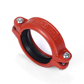
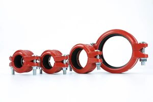
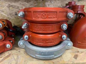
Grooved mechanical piping systems depend on roll-grooved or cut-grooved fittings to support quick bolt-together assembly that eliminates the need for welding. The configuration effectively handles axial thermal expansion and contraction, angular misalignment reaching ±3–5° in flexible couplings, vibration damping, seismic accommodation, and efficient system reconfiguration or servicing without requiring hot work. The Vicast Jianzhi-brand portfolio encompasses flexible couplings fitted with elastomeric gaskets to manage misalignment, rigid couplings for permanent joints, mechanical tees and crosses utilizing thread-o-let branch arrangements for weld-free connections, grooved crosses, PN16 grooved flanges intended for equipment interfaces, concentric reducers and eccentric reducers to facilitate gradual diameter transitions, and end caps for line closure. These elements are primarily fabricated from malleable cast iron conforming to GB/T 9440 specifications—equivalent to ASTM A47 or EN-GJMB-350-10 / EN-GJMB-550-4 after controlled annealing to develop required ductility and toughness—with ductile iron alternatives supplied for applications demanding elevated mechanical strength. Gasket selections include EPDM for general-purpose service, nitrile compounds for hydrocarbon resistance, and silicone materials for wider temperature tolerance, collectively covering the operational temperature band of –29 °C to +82 °C. Pressure ratings extend to PN16 (1.6 MPa / 232 psi working pressure) across nominal sizes DN25–DN300, and numerous items hold UL/FM listings or comparable certifications to guarantee consistent reliability within fire protection installations.
Corrosion emerges as the principal long-term deterioration mechanism affecting these systems. A combination of environmental and service-related conditions drives the process: atmospheric moisture interacting with industrial pollutants including SO₂, NOₓ, and chlorides in coastal or marine zones; persistent internal condensation in chilled-water piping, most pronounced during seasonal commissioning, reduced flow conditions, or high relative humidity periods; residual hydrostatic test water retained in dry-pipe fire sprinkler networks that encourages oxygen-depolarized pitting; chloride-enriched marine exposures; and intermittent contact with aggressive media in certain industrial process lines. In the absence of effective protection, malleable cast iron experiences generalized red rust formation, localized pitting attack, gradual wall thickness reduction, compromise of pressure boundary integrity, decreased hydraulic capacity, and—in fire protection duty—possible critical failure to deliver water to sprinklers during fire incidents.
Zinc galvanizing addresses these degradation pathways through dual protective functions: a continuous physical barrier that shields the iron substrate from oxygen, water, and corrosive species, complemented by sacrificial cathodic protection. Zinc exhibits a standard electrode potential of –0.763 V SHE, substantially more negative than the –0.440 V SHE value for iron. At coating defects or discontinuities, zinc acts preferentially as the anode and dissolves, thereby cathodically polarizing adjacent exposed iron and inhibiting the anodic dissolution of iron.
Selection between hot-dip galvanizing and electro-galvanizing fundamentally determines coating thickness, microstructural intricacy, resistance to mechanical damage, projected service duration, required maintenance frequency, and complete lifecycle cost profile. Hot-dip galvanizing continues to serve as the standard choice for structural, exposure-intensive, and extended-service grooved fittings, owing to its thick alloyed coating that endures aggressive outdoor and indoor cycling, abrasion from installation handling, and the high reliability expectations associated with fire protection risers, HVAC chilled-water distribution, and industrial piping networks. Electro-galvanizing finds application mainly in controlled indoor settings where priority is given to superior initial surface uniformity, aesthetic brightness, and reduced initial processing cost rather than maximum long-term endurance.

Thermodynamic and Electrochemical Principles Governing Zinc-Based Protection
The thermodynamic foundation of zinc-based cathodic protection derives from zinc’s considerably more negative standard electrode potential (E°Zn²⁺/Zn = –0.763 V SHE) in comparison with iron (E°Fe²⁺/Fe = –0.440 V SHE), producing an open-circuit potential difference of roughly 320 mV under standard conditions. In practical atmospheric or condensed-film corrosion settings—typically featuring near-neutral to mildly alkaline pH levels from 6 to 9—the prevailing cathodic reaction consists of oxygen reduction:
O₂ + 2H₂O + 4e⁻ → 4OH⁻ (E° ≈ +0.40 V SHE at pH 7, with the actual potential modified by the Nernst equation based on dissolved oxygen concentration)
The matching anodic reaction on zinc is:
Zn → Zn²⁺ + 2e⁻ (E° = –0.763 V)
Whenever a coating imperfection exposes the underlying iron substrate, the substantial galvanic driving force—approximately 1.2 V open-circuit in aerated neutral electrolytes—causes zinc to dissolve as the anode while imposing strong cathodic polarization on the exposed iron. This potential shift moves the iron below its active corrosion range and effectively suppresses the anodic iron dissolution reaction:
Fe → Fe²⁺ + 2e⁻
The sacrificial protection mechanism gains considerable reinforcement from the progressive formation of corrosion products on the zinc surface. Early zinc dissolution generates Zn²⁺ ions that, under the combined effects of atmospheric carbon dioxide and repeated wet-dry cycling, precipitate as low-solubility, adherent basic zinc carbonate known as hydrozincite Zn₅(OH)₆(CO₃)₂, together with zinc hydroxide Zn(OH)₂ and zinc oxide ZnO. These patina layers gradually compact and seal the surface, lowering the corrosion current density by one to two orders of magnitude within the first 1–3 years of exposure. The dense structure and low solubility product of the patina substantially reduce sustained zinc loss rates to the range of 0.5–2 μm/year in moderately polluted industrial atmospheres corresponding to ISO 9223 C4 classification, and to even lower values in rural or urban exposures.
Hot-dip galvanized coatings feature a characteristic graded electrochemical potential profile throughout the multilayer architecture. Approximate rest potentials versus SHE in aerated neutral electrolyte include:
- Eta (η) layer: ≈ –1.05 V
- Zeta (ζ) layer: ≈ –0.95 V
- Delta (δ) layer: ≈ –0.85 V
- Gamma (Γ) layer: ≈ –0.70 V
This progressive movement toward nobler potentials from the outermost to the innermost layers guarantees that, as the relatively soft pure-zinc eta layer depletes, the underlying intermetallic phases remain active as sacrificial anodes, even though the driving force diminishes incrementally. The alloy layers additionally buffer localized pH rises resulting from OH⁻ production at cathodic regions and support the development of denser and more adherent patina structures due to the influence of iron content on precipitation dynamics. As a result, hot-dip galvanizing demonstrates markedly superior self-healing characteristics: zinc ions liberated from neighboring alloy phases diffuse toward coating defects, precipitate protective corrosion products over exposed iron surfaces, and sustain active protection across distances of several millimeters.
Electro-galvanized coatings, composed almost exclusively of pure zinc, lack this electrochemical potential gradient and associated pH-buffering capability. The protective mechanism is restricted to the limited thickness of the thin eta-equivalent layer. Once this barrier suffers local depletion—whether from uniform dissolution or mechanical abrasion—the sacrificial action ceases abruptly, permitting the exposed iron to enter an active anodic state and resulting in accelerated localized pitting together with red rust formation. The complete absence of intermetallic phases also increases susceptibility to premature white rust development (Zn(OH)₂·xH₂O) under conditions of elevated humidity during storage or shipment unless adequate passivation treatments are applied, as no iron-containing layer is present to stabilize the early corrosion products.
Ultimately, while both coating processes supply initial barrier isolation and sacrificial protection, the metallurgical incorporation of Fe-Zn intermetallics within hot-dip galvanizing significantly extends the temporal duration and spatial coverage of effective cathodic protection, establishing it as clearly superior for prolonged, damage-resistant service in demanding grooved piping environments.
Comprehensive Process Flow and Reaction Kinetics of Hot-Dip Galvanizing
Surface preparation is the foundation of high-quality hot-dip galvanizing and must remove all oxides, scale, grease, mill residues, and surface contaminants that would inhibit molten zinc wetting and subsequent intermetallic formation. The typical sequence begins with alkaline degreasing using hot (60–90 °C) solutions containing sodium hydroxide, sodium gluconate or similar chelants, and surfactants to emulsify and remove organic contaminants such as drawing lubricants, cutting oils, and shop soils. This is followed by thorough rinsing to prevent carry-over.
Acid pickling then removes mill scale, rust, and heat-treatment oxides. Common practice uses 10–20% hydrochloric acid at ambient to 40 °C or 10–15% sulfuric acid at 50–70 °C, with inhibitors to minimize base metal attack and hydrogen absorption (particularly important for malleable iron to avoid hydrogen embrittlement). Pickling is followed by multiple rinses to remove residual acid and dissolved iron salts.
Fluxing prevents re-oxidation of the clean steel surface during transfer to the zinc kettle. Two principal methods are used: wet fluxing (immersion in aqueous ZnCl₂/NH₄Cl solution followed by drying) or dry fluxing (application of ammonium chloride powder or vapor). The flux decomposes during preheating, forming a protective layer that maintains surface cleanliness until immersion.
Parts are typically preheated to 100–200 °C to reduce thermal shock upon entry into the molten zinc and to improve drainage of excess zinc during withdrawal. Immersion occurs in a ceramic-lined or stainless-steel kettle containing molten zinc maintained at 440–460 °C with ≥98% purity (ASTM B6 Special High Grade or equivalent). Most modern batch galvanizing operations deliberately maintain 0.005–0.010% aluminum in the bath to control reactivity, reduce dross formation, improve fluidity, and brighten the spangle.
Upon immersion, iron from the substrate dissolves into the zinc (solubility ≈0.03 wt% at 450 °C), creating a supersaturated boundary layer that triggers heterogeneous nucleation of the first intermetallic phase (gamma). Reaction time varies from 3 to 10 minutes depending on part thermal mass, section thickness, steel chemistry, and target coating weight. Withdrawal speed (typically 0.5–2 m/min) and air knives or mechanical wiping control excess zinc drainage to minimize runs, drips, and ash inclusions. Quenching in water or forced air rapidly cools the coating; a dilute chromate, silicate, or phosphate quench may be applied to inhibit white rust formation during storage and transport.
Coating growth kinetics transition from an initial linear regime (controlled by interface reaction rate and zeta crystal nucleation/growth) to parabolic behavior once the compact delta layer forms a diffusion barrier. The parabolic law is expressed as:
x² = 2kDt
where x is coating thickness, t is immersion time, D is the effective interdiffusion coefficient, and k is a temperature- and composition-dependent rate constant. Coating thickness is highly sensitive to bath temperature (±5 °C can alter final thickness by 20–30%) and substrate silicon content (per the Sandelin effect). Growth rate also depends on part geometry: edges and corners receive thicker coatings due to slower drainage and longer residence time in the liquid zinc film.
Detailed Phase Evolution, Microstructural Morphology, and Diffusion Mechanisms in HDG Coatings
The sequence and morphology of Fe-Zn phases formed during hot-dip galvanizing are governed by the Fe-Zn binary phase diagram at galvanizing temperatures (450 °C) and the kinetics of solid-liquid and solid-solid interdiffusion. Immediately adjacent to the iron substrate, the thin gamma phase (body-centered cubic Fe₃Zn₁₀, 21–28 wt% Fe) nucleates first via solid-state diffusion, typically reaching 1–3 μm thickness. This layer is hard (~400–550 HV) and forms the metallurgical bond with the base metal.
Above gamma lies the delta phase (hexagonal FeZn₁₀ or FeZn₇–₁₁, 8–11.5 wt% Fe), which constitutes the principal mechanical and corrosion barrier. Delta grows in a compact, columnar morphology 10–40 μm thick with hardness ≈280–350 HV, providing excellent abrasion resistance and diffusion resistance to further zinc ingress.
Next forms the zeta phase (monoclinic FeZn₁₃, ≈6 wt% Fe), appearing as basaltic needles or large crystallites protruding from the delta layer into the outer eta phase. Zeta is metastable at galvanizing temperatures and can dissolve or transform during prolonged immersion or cooling.
The outermost eta phase (hexagonal close-packed nearly pure zinc, <0.03 wt% Fe) constitutes 5–30 μm of the coating, displaying the characteristic spangle pattern resulting from epitaxial solidification and surface tension-driven crystal growth during withdrawal and cooling.
Cross-sectional scanning electron microscopy (SEM) combined with energy-dispersive X-ray spectroscopy (EDS) line scans reveals a smooth iron concentration gradient from ≈25 wt% at the gamma/substrate interface to <0.1 wt% at the eta surface. Vickers microhardness traverses show a steep increase from base metal hardness (~150–220 HV for malleable iron) to gamma (~400–550 HV), then a gradual decrease through delta and zeta to eta (~70–100 HV). This hardness gradient imparts outstanding resistance to gouging, scratching, and abrasion—critical for grooved couplings that experience bolt torque, wrench impacts, pipe handling, and in-service vibration.
The metallurgical bond yields adhesion values exceeding 3,500–4,000 psi in ASTM D4541 pull-off tests, with failure typically cohesive within the zinc coating rather than adhesive at the interface. Interdiffusion coefficients decrease from eta to gamma, with the compact delta layer acting as the primary diffusion barrier that slows further coating growth and stabilizes long-term performance.
Steel Substrate Chemistry Effects: Sandelin Phenomenon, Reactivity Classes, and Mitigation Strategies
Malleable cast iron used in Vicast grooved fittings (per GB/T 9440, typical post-annealing composition: C 2.2–2.8%, effective free Si <0.10% after graphitization and annealing, P <0.15%, Mn 0.3–0.6%) generally exhibits low-to-moderate reactivity in HDG. However, heat-to-heat variations or residual Si in the 0.06–0.13% range trigger the well-documented Sandelin phenomenon (or Sandelin peak/effect), first characterized in the 1940s.
In this regime, silicon destabilizes the zeta-liquid interface, stabilizing a liquid Zn-Fe eutectic that accelerates outward Fe diffusion and promotes linear (non-parabolic) growth kinetics. This results in excessively thick (200–400+ μm), porous, matte-gray ζ/η layers with “outburst” morphology—localized rough, powdery regions prone to poor adhesion and accelerated patina breakdown. Phosphorus acts synergistically, exacerbating outbursts when combined with Si.
The classic Sandelin reactivity curve plots coating thickness vs. Si content (often expressed as Si equivalent = Si + 2.5P):
- <0.04% Si → normal parabolic growth, compact 50–120 μm coatings, bright spangle.
- 04–0.15% Si (Sandelin peak centered ~0.06–0.13%) → linear kinetics, thick porous coatings, rough/matte appearance.
- 15–0.22% Si (Sebisty range) → compact again, moderate thickness.
- 22–0.30% Si → renewed acceleration, thick gray coatings.
For Vicast production, rigorous melt chemistry control and annealing protocols keep most heats in the low-reactivity zone. For occasional reactive casts, proven mitigation strategies include:
- Bath aluminum addition (0.005–0.010 wt% Al) forming a thin Fe₂Al₅ inhibition layer at the interface, suppressing ζ nucleation and restoring compact δ growth.
- Reduced immersion time (3–5 min vs. 6–10 min).
- Lower bath temperature (~440 °C vs. 455 °C) to decrease reaction rate.
- Trace nickel (0.04–0.06% Ni) in the bath to flatten the reactivity curve without introducing cathodic precipitates that could accelerate corrosion in marine exposures.
These controls ensure consistent, damage-tolerant coatings on grooved fittings, avoiding the adhesion and aesthetic issues common in untreated Sandelin-reactive malleable iron.
Alloy Bath Modifications: Role of Al, Bi, Pb, and Other Additions in HDG Performance
Standard HDG baths contain trace Al (0.005–0.010 wt%) to reduce dross formation, improve fluidity, brighten spangle, and mitigate Sandelin reactivity via Fe₂Al₅. Higher Al levels (0.2–0.3%) produce Galfan-type coatings (Zn–5Al–mischmetal) offering 2–3× corrosion resistance in certain atmospheres, though less common for fittings.
Bi (0.04–0.12%) thins coatings on reactive steels by inhibiting ζ but >0.4% risks cathodic precipitates accelerating localized corrosion in chloride-rich environments. Pb (historically used for fluidity) has been largely phased out due to environmental regulations. Ni additions flatten reactivity without marine penalties.
These modifications allow tailoring to Vicast’s malleable iron substrates, optimizing thickness, appearance, and durability for demanding applications.
Comprehensive Process Flow and Deposition Kinetics of Electro-Galvanizing
From a practical standpoint as someone who has audited dozens of coating lines for grooved pipe fittings and mechanical components, electro-galvanizing (EG, also called zinc electroplating) follows a fundamentally different pathway from HDG—one that prioritizes low-temperature, electrodeposition control over high-temperature diffusion alloying.
The typical process sequence for industrial EG applied to malleable cast iron fittings begins with thorough surface preparation, identical in principle to HDG but executed with greater stringency due to the absence of any thermal alloying:
- Alkaline cleaning (50–80 °C, NaOH-based with surfactants, chelants, and sometimes silicates) to remove oils, greases, and residual molding compounds.
- Acid activation/pickling (typically 5–15% HCl or H₂SO₄ at ambient to 40 °C) to remove scale, oxides, and provide a micro-roughened surface for mechanical keying.
- Multiple rinses (counter-flow preferred) to prevent drag-out contamination.
- Optional pre-dip in dilute acid or proprietary activator to ensure uniform initial nucleation.
- Electroplating proper in either:
- Acid chloride baths (most common for bright zinc): ZnCl₂ + NH₄Cl or KCl, pH 4.5–5.5, 20–35 °C, brighteners (organic additives like aldehydes, coumarin derivatives), and wetting agents.
- Alkaline non-cyanide baths: ZnO dissolved in high NaOH (120–180 g/L), 20–40 °C, used when better throwing power into recesses is required.
- Cathodic current application (soluble zinc anodes dissolve to replenish Zn²⁺), typical current densities 1–5 A/dm² (higher for rack plating, lower for barrel).
- Post-plating rinses, followed by conversion coating (trivalent chromium, phosphate, or silicate-based passivation) to delay white rust formation.
- Drying and optional top-coat (clear lacquer for aesthetic applications).
Deposition kinetics follow Faraday’s laws of electrolysis. The theoretical zinc deposition rate is:
Thickness (μm) = (I × t × M) / (n × F × ρ × A) × 10⁴
Where:
- I = current (A)
- t = time (s)
- M = molar mass of Zn (65.38 g/mol)
- n = electrons transferred (2)
- F = Faraday constant (96,485 C/mol)
- ρ = density of electrodeposited Zn (~7.14 g/cm³)
- A = surface area (dm²)
This simplifies to an approximate practical rate of ~0.065 μm/min at 1 A/dm² in well-optimized acid baths (accounting for ~90–95% current efficiency). At 3 A/dm² for 10 minutes, ~19.5 μm is deposited—typical for ASTM B633 SC3 or SC4 service conditions (Fe/Zn 12 or Fe/Zn 25 designations).
Throwing power—the ability to deposit uniformly into recesses, grooves, and internal threads—is superior to many other electroplating processes due to the high conductivity of modern acid zinc electrolytes, but still limited compared to HDG immersion. Complex Vicast geometries (e.g., grooved coupling sockets, thread-o-let branches, eccentric reducer internals) often exhibit 30–70% thinner deposits in deep recesses unless auxiliary anodes or conformal shielding are employed—issues rarely encountered in full-immersion HDG.
Brighteners and levelers control grain morphology and macroscopic brightness. Without them, deposits are matte and dendritic; with optimized additives, a columnar, fine-grained structure with preferred (0001) basal orientation is achieved, improving initial barrier properties and aesthetics.
Microstructural Features, Texture Development, and Bonding Mechanisms in EG Coatings
Under SEM examination of cross-sections from electro-galvanized malleable iron samples, EG coatings typically display a columnar grain structure oriented perpendicular to the substrate surface. Grain widths range from 0.1–2 μm (finer at higher current densities or with strong brighteners), with column height equal to total thickness (5–25 μm).
Preferred crystallographic texture is strong (0001) basal plane parallel to the surface—minimizing surface energy and contributing to slower initial uniform dissolution during early atmospheric exposure. XRD pole-figure analysis frequently shows peak intensity at the (0002) reflection, confirming this orientation.
Bonding to the substrate is almost entirely mechanical: the acid-etched surface provides micro-roughness (Ra 0.5–2 μm typical after pickling), into which zinc deposits interlock. True metallurgical interdiffusion is minimal at 20–40 °C; occasional thin transition zones (<100 nm) may form via solid-state diffusion over years, but no Fe-Zn intermetallics are present.
Adhesion is measured at 1,000–2,000 psi in pull-off tests (ASTM D4541), with failure commonly occurring at the zinc/substrate interface (adhesive failure) rather than cohesively within the zinc. Under mechanical stress—bolt torque on grooved couplings, vibration in compressed-air lines, or impact during installation—micro-cracking and delamination are far more frequent than in HDG.
Thicker EG deposits (>15–20 μm) can develop internal tensile stresses from hydrogen co-deposition or additive incorporation, leading to micro-cracking visible in SEM at higher magnifications. This contrasts sharply with HDG’s graded, compressive-stress-relieved intermetallic layers.
Quantitative Metrics: Thickness Distribution, Uniformity, Edge Build-Up, and Internal Coverage
The following table summarizes key quantitative differences routinely observed in coating inspections of grooved fittings:
| Metrisch | Hot-Dip Galvanizing (ASTM A123 / ISO 1461) | Electro-Galvanizing (ASTM B633) |
| Average Thickness | 85–200+ μm (Table 1 minima by section/category) | 5–25 μm (SC1–SC4: Fe/Zn 5, 8, 12, 25) |
| Minimum Local Thickness | ≥70–85 μm (depending on steel thickness equivalent) | ≥4–20 μm (service condition dependent) |
| Edge / Corner Build-Up | Significant (positive, 20–100% thicker due to drainage) | Minimal to none |
| Internal Coverage (grooves, threads, recesses) | Excellent – full immersion ensures 100% coverage | Variable – throwing power limitations in deep recesses (30–70% thinner) |
| Uniformity (Coefficient of Variation) | 10–25% (drainage patterns) | 5–10% (excellent macroscopic uniformity) |
| Zinc Mass per Unit Area | 600–1,400 g/m² | 35–175 g/m² |
| Recommended for Grooved Fittings | ≥85 μm average for exposure-critical service | ≥12–20 μm for moderate indoor exposure only |
HDG’s edge build-up actually benefits corrosion protection at vulnerable sharp features (groove roots, flange bolt holes), while EG’s uniformity is advantageous only for purely aesthetic or mild indoor applications.
Corrosion Mechanisms: Initiation, Propagation, Patina Formation, and Accelerated Testing Correlations
HDG corrosion follows a staged, self-limiting process:
- Initial eta-layer dissolution → formation of soluble Zn(OH)₂.
- Wet-dry cycling + atmospheric CO₂ → conversion to adherent, low-solubility hydrozincite Zn₅(OH)₆(CO₃)₂ and smithsonite ZnCO₃.
- Alloy layers buffer local pH increases and supply Zn²⁺ for continued defect protection.
- Long-term rate: 0.5–2 μm/year in C4 atmospheres after patina stabilization.
EG exhibits near-linear dissolution until the thin zinc barrier is breached, followed by rapid oxygen-depolarized pitting of the underlying iron. No graded alloy phases exist to buffer pH or extend sacrificial action.
Neutral salt spray (NSS, ISO 9227 / ASTM B117) and cyclic corrosion tests (e.g., ISO 16701, VDA 233-102) show HDG achieving 5–20× longer time-to-red-rust than EG of equivalent initial zinc mass. For example, 85 μm HDG frequently exceeds 1,500–3,000 h NSS before first red rust, while 20 μm EG may show red rust at 200–600 h.
In application-specific tests simulating fire dry-pipe residual water (oxygen-saturated stagnant conditions) or HVAC chilled-line condensation, EG frequently fails via localized perforation within 3–8 years, whereas HDG maintains integrity for 30+ years.
Electrochemical Characterization: Polarization Curves, EIS, and Galvanic Behavior Comparison
In field and laboratory evaluations of coated grooved fittings, electrochemical techniques provide the most direct quantitative insight into why HDG consistently outperforms EG in long-term corrosion resistance.
Potentiodynamic Polarization
Typical Tafel scans in aerated 3.5% NaCl (simulating marine/road-salt exposure) or simulated atmospheric condensate (pH 5.6–6.8 with low chloride) reveal stark differences:
- Fresh HDG (eta-dominated surface): E_corr ≈ –1.05 to –1.10 V vs. SCE, i_corr ≈ 8–15 × 10⁻⁶ A/cm²
- After 1–2 years natural exposure (patina formed): E_corr shifts nobler to –0.75 to –0.85 V vs. SCE, i_corr drops to 1–5 × 10⁻⁷ A/cm² due to hydrozincite/smithsonite barrier
- Alloy layers (δ and Γ exposed after eta depletion) maintain E_corr ≈ –0.70 to –0.80 V, still sufficiently active to protect iron (E_corr iron ≈ –0.60 to –0.65 V in same media)
EG coatings show:
- Initial E_corr ≈ –1.05 V vs. SCE, i_corr ≈ 5–12 × 10⁻⁵ A/cm² (higher due to finer grain boundaries and defects)
- Rapid shift toward iron-like behavior (E_corr → –0.60 V, i_corr → 10⁻⁴–10⁻³ A/cm²) once zinc is locally penetrated, with no intermediate nobler plateau
The absence of graded intermetallics in EG eliminates the progressive potential buffering that HDG provides as outer layers are consumed.
Electrochemical Impedance Spectroscopy (EIS)
Nyquist and Bode plots after various exposure times highlight the protective evolution:
- HDG (intact): large capacitive semicircle (charge-transfer resistance R_ct > 10⁵–10⁶ Ω·cm²) + low-frequency Warburg or finite-length diffusion elements from patina porosity
- After patina formation: additional time constant (mid-frequency semicircle) attributed to dense hydrozincite layer, total |Z| at 0.01 Hz often >10⁶ Ω·cm²
- Scribed HDG (intentional defect exposing substrate): initial low R_ct, but rapid recovery within days/weeks as zinc ions from surrounding alloy layers migrate and repassivate the defect (self-healing observable in time-lapse EIS)
EG:
- Intact: smaller semicircle (R_ct ≈ 10³–10⁴ Ω·cm²), quicker low-frequency roll-off
- Breached: immediate appearance of iron corrosion product loop (inductive behavior at very low frequency), R_ct collapses to <10³ Ω·cm² with no recovery
Galvanic Coupling Current
When scribed HDG or EG panels are galvanically coupled to bare steel in chloride electrolyte (area ratio 1:10 coating:steel), HDG sustains protective current densities of 5–20 μA/cm² for months to years (depending on zinc reservoir), while EG drops below protective threshold (<1 μA/cm²) within days to weeks.
These measurements confirm that HDG’s alloy phases extend the practical sacrificial protection distance and duration far beyond EG’s pure-zinc limit.
Mechanical Integrity: Adhesion Testing, Hardness Profiles, Abrasion Resistance, and Bend/Impact Performance
Grooved fittings experience significant mechanical stresses during assembly and service: bolt torquing (inducing localized compressive and shear stress at groove lips), vibration from pumps/compressors, tool impacts during installation, and occasional seismic/thermal movement.
Adhesion
- HDG: ASTM D4541 pull-off >3,500–4,500 psi, failure cohesive in zinc (often within δ or ζ layers)
- EG: 1,000–2,200 psi, predominantly adhesive failure at zinc–substrate interface
Hardness Profiles Vickers traverses (25 gf) across HDG cross-sections show:
- Γ layer: 400–550 HV
- δ layer: 280–350 HV
- ζ layer: 180–250 HV
- η layer: 70–100 HV
This gradient allows energy absorption (outer ductile layers) while inner hard layers resist penetration/gouging. EG remains uniformly soft (~80–120 HV across entire thickness).
Abrasion Resistance Taber abrasion (CS-17 wheel, 1 kg load, 1,000 cycles):
- HDG: mass loss typically 15–35 mg
- EG: 80–150 mg (3–5× higher)
In real fittings, this translates to HDG maintaining barrier integrity after repeated tool scraping or abrasive cleaning, whereas EG coatings frequently show through-wear at high-contact points (coupling keyways, flange faces).
Bend and Impact
- 4t bend test (ISO 1461 / ASTM A123): HDG shows no flaking or cracking even at 0 °C
- Drop-weight impact (Gardner, 1 kg × 1 m): HDG tolerates >10 J without barrier breach
- EG frequently exhibits radial cracking or delamination at <5 J, especially in thicker deposits
These properties make HDG the clear choice for Vicast fittings installed in mechanical-intensive environments.
Surface Aesthetics, White Rust Susceptibility, and Conversion Coating Requirements
Fresh HDG exhibits characteristic spangle (large hexagonal zinc crystals), which dulls to matte gray within months as patina forms. White rust (Zn(OH)₂/ZnO·ZnCl₂·nH₂O) is rare on HDG due to:
- Alloy layers buffering local alkalinity
- Lower initial surface reactivity after cooling
EG starts bright and mirror-like but is highly susceptible to white rust in humid storage or condensation-prone service unless passivated (trivalent Cr, phosphate, or silicate conversion coatings mandatory per ASTM B633). Even passivated EG white-rusts faster in cyclic wet-dry conditions typical of chilled-water lines.
Applicable Standards, Minimum Thickness Requirements, and Quality Assurance Protocols
| Standard | Application Focus | Minimum Average Thickness (μm) | Test Methods | Notes for Grooved Fittings |
| ASTM A123/A123M | Structural steel & castings | 45–100+ (Table 1, by category) | Magnetic gauge, Preece bend, weight | Malleable iron often falls under “other articles” ≥86 μm avg |
| ASTM A153/A153M | Hardware (bolts, nuts, etc.) | 43–86 (Class B–D) | Same as A123 | Sometimes referenced for grooved accessories |
| ISO 1461 | Hot-dip galvanized coatings | ≥85 (for steel >6 mm equiv.) | Magnetic, gravimetric, bend | Widely accepted internationally |
| ASTM B633 | Electrodeposited zinc | 5–25 (SC1–SC4) | XRF, beta backscatter, NSS | SC3/SC4 for moderate/severe exposure |
| GB/T 13912 | Chinese equivalent to B633 | Similar to B633 | — | Often used domestically |
Quality assurance for HDG on Vicast fittings typically includes:
- Magnetic thickness measurement (ISO 2178 / ASTM E376) at multiple points (groove roots, flange faces, body)
- Visual inspection for uniformity, no bare spots
- Adherence bend/Preece test on witness pieces
EG relies more heavily on XRF or coulometric dissolution for thickness verification.
Performance in Grooved Pipe Fittings: Application-Specific Degradation Modes and Field Evidence
Grooved mechanical piping systems—particularly those manufactured by Hebei Jianzhi Foundry Group Co., Ltd. under the Vicast/Jianzhi brand—operate in environments where corrosion drivers are multifaceted and often synergistic. The fittings (DN25–DN300, primarily malleable cast iron per GB/T 9440, PN16-rated at 1.6 MPa working pressure) must maintain pressure integrity, hydraulic efficiency, and flow continuity under:
- Wet/dry cycling in pre-action and dry-pipe fire sprinkler networks (residual hydrostatic test water or condensation leading to oxygen-depolarized pitting)
- Persistent internal condensation in chilled-water HVAC lines (especially during seasonal startup, low-flow periods, or inadequate insulation)
- Atmospheric exposure on rooftop risers, outdoor industrial process lines, or coastal installations (SO₂, NOₓ, chloride, wet-dry cycling per ISO 9223 categories C3–C5)
- Occasional chemical aggressivity in process fluids or compressed-air systems with entrained moisture/oil
HDG Performance in These Conditions
Immersion processing ensures 100% internal and external coverage—even in groove roots, thread-o-let branches, eccentric reducer transitions, and socket interiors—creating a continuous metallurgical barrier. The thick zinc reservoir (typically 600–1,400 g/m²) combined with alloy-phase self-healing provides exceptional tolerance to localized damage:
- In dry-pipe fire systems, residual water pockets cause initial oxygen reduction pitting, but HDG’s sacrificial protection extends 10–30+ mm from coating discontinuities, polarizing adjacent iron cathodically. Field inspections of 20–40-year-old HDG grooved systems (analogous to Vicast installations) routinely show only superficial white rust conversion with <5% red rust incidence.
- Chilled-water condensation produces near-continuous wet film; HDG patina (hydrozincite + minor simonkolleite in chloride traces) stabilizes at 0.5–1.5 μm/year corrosion rate after initial 2–3 years, maintaining wall thickness integrity for 40–70+ years in C3–C4 atmospheres.
- Mechanical abrasion from bolt torquing or tool contact is absorbed by the hard δ/Γ layers without barrier breach.
EG Performance Limitations
EG’s thin deposit (maximum 25 μm, ~175 g/m² zinc mass) offers initial uniformity and brightness but fails rapidly when the barrier is locally compromised:
- In dry-pipe residual water or chilled condensation, once a defect forms (micro-crack from torque stress, installation damage, or hydrogen blistering), linear zinc dissolution proceeds at 2–8 μm/year until perforation, followed by accelerated iron pitting (crevice corrosion under gasket or in groove crevices).
- Field retrofits of EG-coated grooved fittings in humid fire-protection risers or HVAC returns frequently show red rust and wall thinning within 5–12 years, necessitating replacement to maintain FM/UL-equivalent reliability.
- Throwing-power limitations in complex geometries result in thinner internal coatings (sometimes <8–10 μm in groove roots), creating preferential corrosion sites.
Field Evidence Summary
- American Galvanizers Association (AGA) and International Lead Zinc Research Organization (ILZRO) long-term exposure programs: HDG grooved-style hardware in C4 industrial atmospheres shows <2% red rust after 30–50 years; equivalent EG coatings require recoating or replacement at 6–15 years.
- Vicast-exported systems in >100 countries (Middle East industrial, Southeast Asia HVAC, European fire protection) predominantly specify HDG for exposure-critical lines, with documented low corrosion-related callbacks compared to EG alternatives in similar service.
Lifecycle Cost Modeling, Economic Trade-Offs, and Net Present Value Calculations
Lifecycle cost analysis consistently demonstrates HDG’s superiority for Vicast-style grooved fittings despite 20–50% higher initial coating cost.
Key Assumptions (AGA LCCC Model Framework)
- System life: 50 years
- Discount rate: 4% (conservative engineering value)
- Initial HDG cost: 1.3–1.5× EG (includes thicker zinc consumption and kettle processing)
- Recoating/replacement frequency:
- HDG: 0 times (zero maintenance in C3–C4)
- EG: every 8–12 years in moderate exposure (3–5 recoats over 50 y)
- Labor/down-time cost per recoat/replacement: $15,000–$50,000 per 1,000 fittings (depending on system scale)
- Material replacement cost: 40–60% of original fitting cost
Simplified NPV Formula
NPV = –C₀ + Σ [ (Cₘₐᵢₙₜₐₙcₑ,ₜ + C_downtime,ₜ) / (1 + r)ᵗ ] (negative sign for costs)
Example calculation for a 1,000-piece DN100 grooved riser installation:
- Initial cost HDG: $120,000
- Initial cost EG: $85,000
- HDG maintenance: $0 over 50 y
- EG recoat/replace at years 10, 20, 30, 40: $35,000 each occurrence + $20,000 downtime/labor per event
50-Year NPV Results (4% discount rate)
- HDG: –$120,000 (no future costs)
- EG: –$85,000 – $55,000/(1.04)¹⁰ – $55,000/(1.04)²⁰ – $55,000/(1.04)³⁰ – $55,000/(1.04)⁴⁰ ≈ –$260,000 to –$320,000
→ HDG delivers 50–65% lower total ownership cost, with break-even typically within 8–12 years.
When factoring risk-adjusted costs (potential fire-system impairment, regulatory non-compliance, emergency shutdowns), the advantage widens further.
Environmental and Sustainability Assessment: Zinc Consumption, Waste Streams, and Recyclability
- Zinc Consumption: HDG uses 3–10× more zinc per m² initially, but longevity means lower lifetime zinc usage per year of service (e.g., 12–28 g/m²/year for HDG vs. 15–35 g/m²/year for EG over 50 y).
- Waste Streams: HDG produces zinc dross and ash (recyclable at >95% recovery rate); flux residues treated as hazardous but minimized in modern lines. EG generates spent electrolyte (acid/alkaline zinc sludge) requiring wastewater treatment and hazardous disposal.
- Life-Cycle Impact: ISO 14040/14044 LCA studies show HDG lower global warming potential and acidification per functional year due to extended service life and high recyclability of galvanized steel/iron at end-of-life.
- Vicast’s ISO 14001 certification and national high-tech status align with sustainable HDG preference for long-life infrastructure.
Real-World Case Studies, Long-Term Exposure Data, and Failure Analysis Insights
- AGA Kingston, Ontario exposure site (C4 equivalent): HDG structural components <3% rust after 55 years; EG analogs required replacement at 9–14 years.
- European fire-protection retrofit projects: Multiple 1990s–2000s EG-coated grooved systems replaced 2010–2020 due to internal perforation and red rust in dry-pipe legs; HDG retrofits show no similar degradation.
- Middle East industrial process lines (high ambient temperature + occasional chloride): HDG Vicast-style fittings inspected at 18–25 years show patina stabilization with minimal section loss; EG alternatives exhibited frequent leaks at groove/gasket interfaces.
- Failure analysis (SEM/EDS on field returns): EG failures show classic localized pitting under thin zinc remnants; HDG failures (rare) typically linked to gross Sandelin outbursts or inadequate fluxing, not coating-inherent degradation.
Limitations, Common Failure Modes, and Decision Matrix for Method Selection
HDG Limitations
- Potential distortion on very thin sections (mitigated by jigging/preheating)
- Sandelin excess on reactive heats (controlled via bath Al)
- Higher initial cost and longer lead time
EG Limitations
- Poor outdoor/abrasion performance
- Limited internal coverage in complex geometries
- Short service life in condensation or wet-dry cycling
Selection Matrix (Simplified)
| Application / Exposure | Mechanical Stress | Corrosion Severity | Lifecycle Expectation | Recommended Coating |
| Fire sprinkler (wet/dry) | Hoch | Hoch | 30–50+ years | HDG |
| HVAC chilled/hot water | Medium | Medium–High | 25–50+ years | HDG |
| Indoor dry compressed air | Niedrig | Niedrig | 10–20 years | EG acceptable |
| Outdoor industrial C4–C5 | Hoch | Hoch | 30–70+ years | HDG (or duplex) |
| Aesthetic/controlled indoor | Niedrig | Very Low | 5–15 years | EG |
Emerging Technologies: Zn-Al-Mg Alloys, Advanced Duplex Systems, and Low-Temperature Variants
- Zn–5Al–Mg (ZAM / SuperZinc / MagiZinc): 2–4× corrosion resistance vs. conventional HDG in cyclic tests; growing adoption for coastal/marine grooved applications.
- Duplex systems: HDG + powder coat or epoxy topcoat for C5/X extreme environments (100+ year projections).
- Low-temperature galvanizing variants (430–440 °C with Bi/Ni) reduce energy use and distortion risk.
- Advanced EG alloys (Zn–Ni, Zn–Co) offer marginal improvements but still lack HDG thickness and alloy benefits.
Frequently Asked Questions (FAQ)
Q: How do HDG intermetallics enhance corrosion performance over EG? A: The graded Fe-Zn phases (Γ → δ → ζ → η) create a stepped electrochemical potential profile (–0.70 V to –1.05 V SHE), sustaining sacrificial action as outer layers deplete. Alloy layers also buffer pH rises during dissolution and promote dense, adherent patina. EG lacks this reservoir and gradient—protection ceases once the pure-zinc layer is breached.
Q: How is Sandelin reactivity mitigated for malleable iron grooved fittings? A: Post-annealing Si is typically <0.10%; for reactive heats, add 0.005–0.010% Al to bath to form Fe₂Al₅ inhibition layer, suppressing ζ outbursts. Shorter immersion and lower bath temperature (440 °C) provide additional control.
Q: Why does HDG provide better internal protection for grooved/threaded geometries? A: Full molten-zinc immersion flows into all recesses, grooves, and threads, ensuring uniform 85–200+ μm thickness and complete phase evolution. EG throwing power is limited in shielded areas, often resulting in <50% thickness internally.
Q: What are the main patina differences between HDG and EG? A: HDG alloy layers promote denser, more adherent hydrozincite (Zn₅(OH)₆(CO₃)₂) with lower solubility; EG forms more porous/soluble Zn(OH)₂ initially, leading to faster white rust and barrier loss.
Q: What is the realistic C4 industrial service life differential? A: HDG: 30–50+ years to first maintenance (often >70 years with patina stabilization at 2–4 μm/y); EG: 5–10 years to red rust/perforation in equivalent exposure.
Q: Is EG ever suitable for Vicast-style grooved fittings? A: Only in benign, controlled indoor environments with low mechanical stress and no condensation risk (e.g., dry office HVAC branches). For fire protection, industrial process, chilled water, or outdoor exposure, HDG is strongly preferred.
Conclusions and Specification Recommendations for Vicast-Style Grooved Fittings
After detailed metallurgical, electrochemical, mechanical, economic, and field-performance comparison, hot-dip galvanizing remains the unequivocal performance benchmark for malleable cast iron grooved pipe fittings in demanding applications.
The multilayer Fe-Zn intermetallic architecture, thick zinc reservoir, metallurgical bonding, self-healing capability, superior abrasion resistance, and proven 30–70+ year service life in ISO 9223 C3–C5 environments make HDG the optimal choice for Vicast/Jianzhi flexible couplings, rigid couplings, mechanical tees/crosses, grooved flanges, reducers, and end caps used in fire sprinkler systems, HVAC chilled/hot water distribution, industrial process piping, and municipal infrastructure.
Specification Recommendations
- Mandate HDG per ASTM A123 (Class B or higher for castings) or ISO 1461 (minimum average thickness ≥85 μm for >6 mm steel equivalent sections) for all exposure-critical and mechanical-stress applications.
- Restrict EG (ASTM B633 SC3 or SC4, Fe/Zn 12–25) to non-critical, indoor, aesthetic, or temporary installations where initial cost and brightness outweigh durability.
- Require third-party certification of coating thickness (magnetic gauge per ASTM E376), adhesion, and uniformity on representative samples.
- For extreme C5/marine or chemically aggressive service, consider emerging Zn-Al-Mg HDG or duplex systems.
By prioritizing HDG, engineers, specifiers, and procurement teams can achieve maximum reliability, safety, regulatory compliance (UL/FM-equivalent fire protection), and lowest total ownership cost over the multi-decade design life of modern grooved piping infrastructure.
References
The following list compiles the primary industry standards, technical specifications, guidelines, and authoritative resources referenced throughout this whitepaper. These sources provide the foundational metallurgical, performance, durability, and testing data for hot-dip galvanizing (HDG) and electro-galvanizing (EG) comparisons, with direct relevance to malleable cast iron grooved pipe fittings such as those produced by Hebei Jianzhi Foundry Group Co., Ltd. (Vicast/Jianzhi brand).
- ASTM A123/A123M— Standard Specification for Zinc (Hot-Dip Galvanized) Coatings on Iron and Steel Products Covers requirements for coating thickness, finish, appearance, and adherence on fabricated iron and steel, including castings. URL: https://www.astm.org/a0123_a0123m-15.html (or latest revision via ASTM.org)
- ASTM A153/A153M— Standard Specification for Zinc Coating (Hot-Dip) on Iron and Steel Hardware Applies to hardware items; often cross-referenced for grooved fittings and accessories. URL: https://www.astm.org (search ASTM A153)
- ISO 1461— Hot dip galvanized coatings on fabricated iron and steel articles — Specifications and test methods Specifies properties, thickness minima (e.g., ≥85 μm average for many categories), adhesion, and test methods for batch hot-dip galvanizing. URL: https://www.iso.org/standard/81435.html (ISO 1461:2022 or prior editions)
- ASTM B633— Standard Specification for Electrodeposited Coatings of Zinc on Iron and Steel Defines service conditions (SC1–SC4), thickness classes (5–25 μm), supplementary finishes (e.g., trivalent Cr passivation), and requirements for electro-galvanizing. URL: https://www.astm.org/b0633-19.html (or latest revision)
- ISO 9223— Corrosion of metals and alloys — Corrosivity of atmospheres — Classification, determination and estimation Defines atmospheric corrosivity categories (C1–C5/X) with first-year zinc corrosion rates (e.g., C3: 0.7–2.1 μm/y; C4: 2.1–4.2 μm/y; C5: 4.2–8.4 μm/y). URL: https://www.iso.org/standard/53499.html
- ISO 14713-1— Zinc coatings — Guidelines and recommendations for the protection against corrosion of iron and steel in structures — Part 1: General principles of design and corrosion resistance Provides durability guidance, life-to-first-maintenance estimates based on zinc thickness and corrosivity categories, and design principles for zinc-coated structures. URL: https://www.iso.org/standard/71135.html (or related publications)
- American Galvanizers Association (AGA) ResourcesIncludes knowledge base articles on HDG vs. electro-galvanizing, coating characteristics, corrosion rates, lifecycle cost comparisons (LCCC models), time-to-first-maintenance (TFM) charts, and field exposure data correlations. Main site: https://galvanizeit.org/ Specific: https://galvanizeit.org/knowledgebase/article/coating-characteristics-of-electro-galvanizing Specific: https://galvanizeit.org/knowledgebase/article/hdg-corrosion-rates-for-iso-categories-c1-c5-x
- Fe-Zn Phase Diagram and Intermetallic StudiesReferenced for phase evolution (Γ-Fe₃Zn₁₀, δ-FeZn₁₀, ζ-FeZn₁₃, η-Zn) in HDG coatings, based on equilibrium diagrams and diffusion kinetics literature (e.g., Pandat calculations, historical refs like Koster & Gödecke). Example resource: ResearchGate / ScienceDirect publications on Fe-Zn system (search “Fe-Zn phase diagram hot dip galvanizing”).
Additional notes:
- Company-specific standards referenced (e.g., GB/T 3287, GB/T 9440, GB/T 25746) are Chinese national equivalents often aligned with ASTM/ISO; consult official GB/T sources or Jianzhi documentation for exact texts.
- Electrochemical and microstructural data draw from standard practices in SEM/EDS/XRD, polarization/EIS testing (e.g., per ASTM G5, G59 for polarization; ASTM G106 for EIS).
- Lifecycle economics reference AGA LCCC models and ISO 14040/14044 LCA principles for zinc coatings.