Abstract
Fire protection systems are the last line of defense in life safety and property protection. For decades, welded, threaded, and flanged joints have been the conventional methods for joining steel pipe in fire sprinkler systems. However, تجهيزات الأنابيب المخدودة have emerged as a mechanically superior alternative that meets or exceeds all applicable fire protection standards while offering significant advantages in installation speed, seismic resilience, and long-term maintainability.
This engineering design guide examines the technical requirements for grooved fittings for fire protection systems as defined by NFPA 13 (Standard for the Installation of Sprinkler Systems) and FM Approvals standards. Drawing on AWWA C606 (groove geometry), ASTM A536 (ductile iron properties), ASTM D2000 (gasket materials), classical elasticity theory, fluid transient analysis, and field data from over 4,500 installations, we provide a comprehensive framework for specifying, selecting, and installing grooved piping system components in fire protection applications.
The guide covers the fundamental mechanics of self-energizing gasket seals, including the governing equation: σ_seal = σ_initial + (P × A_contact / A_gasket) . This principle explains why grooved couplings seal tighter as internal pressure increases—a critical safety feature for fire protection systems that may sit idle for years before activation.
Key topics include NFPA 13 Section 7.4.2, UL 213 and FM 1920 certification criteria for FM approved pipe fittings, pressure ratings and temperature limits, seismic design with flexible couplings (ASCE 7-16), water hammer damping via the Joukowsky equation (ΔP = ρ × a × Δv), installation QA/QC protocols validated to achieve <0.5% failure rate, Failure Mode and Effect Analysis (FMEA), comparative lifecycle cost analysis over 20 years, and a detailed field case study.
Manufacturing capabilities from Hebei Jianzhi Foundry Group Co., Ltd. (Vicast) —a UL/FM approved foundry with over 40 years of ductile iron casting experience, ISO 9001/14001 certification, over 200 patents, active participation in 6 Chinese national standards (GB/T3287, GB/T9440, GB/T25746 and others), and distributors in over 100 countries—are referenced throughout to illustrate real‑world compliance and engineering excellence.
Key conclusions: تجهيزات الأنابيب المخدودة, when engineered to AWWA C606 tolerances, manufactured from ASTM A536 Grade 65-45-12 ductile iron (minimum 12% elongation), and installed per NFPA 13 and manufacturer instructions, achieve pressure ratings equal to or exceeding Schedule 40 steel pipe (Class 150: 1.6 MPa, Class 250: 2.5 MPa, Class 350: 3.5 MPa), survive seismic inter‑story drift of 70 mm per flexible coupling, reduce installation labor by 50–70%, lower total installed cost by 12–25%, eliminate hot work hazards, and reduce 20‑year lifecycle carbon footprint by 45% compared to welded systems. The question is no longer if grooved systems should be used for fire protection—but how to optimize their specification and installation for maximum reliability.

Key Takeaways
| Takeaway | Description |
| NFPA 13 compliance | Section 7.4.2 explicitly permits grooved couplings for steel pipe fire sprinkler systems. Chapter 18 seismic requirements can be met using flexible grooved couplings. |
| FM/UL certification | FM approved pipe fittings must meet FM 1920 or UL 213 requirements, including 4× pressure hydrostatic test, 30‑cycle seismic test, and 500‑hour salt spray corrosion test. Vicast products carry both certifications. |
| Self‑energizing seal | Governing equation: σ_seal = σ_initial + (P × A_contact / A_gasket). The seal becomes tighter as internal pressure increases—unique to grooved couplings. |
| Pressure ratings | Class 150 (1.6 MPa / 232 psi) for 2″–24″; Class 250 (2.5 MPa / 363 psi) for 2″–12″; Class 350 (3.5 MPa / 508 psi) for 2″–8″. Ratings equal or exceed Schedule 40 steel pipe. |
| Temperature limits | Standard EPDM gaskets: −30°C to +120°C continuous service. High‑temperature FKM gaskets available for special applications up to 200°C. |
| Seismic capacity | Flexible couplings provide ±1.0° angular deflection → ≈70 mm lateral displacement per floor (for 4 m story height). Tested to ISO 7386 and FM 1950. |
| Water hammer damping | Flexible couplings reduce effective wave speed from ≈1,200 m/s (welded rigid pipe) to ≈850 m/s, cutting surge pressure by 30% per Joukowsky equation: ΔP = ρ × a × Δv. |
| Installation speed | 6× faster than welding: 10 minutes for an 8″ grooved joint vs. 60 minutes for welded joint (time‑motion data from 120+ construction sites). |
| Labor efficiency | Grooved crew: 2 mechanical fitters. Welded crew: 1 certified welder + 1 fitter + 1 fire watch. Effective labor cost per 8″ joint: welded $155 vs. grooved $12 (plus coupling cost). |
| Leak and rework rates | Field data from 4,500+ installations (2018–2025): leak rate <1% for grooved vs. 10–15% for welded; rework required: 12% for welded vs. 0.5% for grooved. |
| Total installed cost (TIC) | For 500m, 8″ fire sprinkler main: welded TIC $42,600 vs. grooved TIC $25,328 (40.5% lower). Savings increase with pipe diameter: 46% saving for 12″ pipe. |
| Lifecycle cost | 20‑year total cost for same 500m, 8″ line: welded $76,600 vs. grooved $29,928 (61% lower). Includes annual inspection, modifications, and unplanned downtime. |
| Greenhouse gas emissions | 20‑year lifecycle: welded 42 t CO₂e vs. grooved 23 t CO₂e (45% lower)—supports LEED, BREEAM, and Envision green building certifications. |
| Standards participation | Vicast participated in revision of 6 national standards (GB/T3287, GB/T9440, GB/T25746), 5 industry standards, and 4 group standards. Over 200 patents. |
| Global reach | Vicast distributors cover over 100 countries worldwide; factory area 1.4 million m²; ≈4,500 employees including over 350 technical engineers. |
جدول المحتويات
Introduction: The Role of Grooved Fittings in Modern Fire Protection
NFPA 13 Requirements for Grooved Pipe Fittings
FM and UL Certification Standards for Fire Protection Fittings
Material Specifications: Ductile Iron (ASTM A536) and Gaskets (ASTM D2000)
Groove Geometry: AWWA C606 Tolerances and Verification
The Mechanics of Self‑Energizing Seals
Pressure Ratings and Temperature Limits for Fire Systems
Seismic Design with Flexible Grooved Couplings (ASCE 7-16)
Water Hammer Damping in Fire Protection Systems (Joukowsky Equation)
Installation QA/QC: 9‑Step Protocol for Fire Sprinkler Systems
Failure Mode and Effect Analysis (FMEA) for Grooved Fire Systems
Field Case Study: 50‑Story High‑Rise in Dubai
Lifecycle Cost Comparison: Grooved vs. Welded
Manufacturing Excellence: Vicast’s UL/FM Approved Production
Common Design Errors and How to Avoid Them
Future Directions: Smart Couplings and Low‑Carbon Ductile Iron
Conclusion: Engineering Confidence with Grooved Fittings
References
FAQs (16 questions with detailed answers)
1. Introduction: The Role of Grooved Fittings in Modern Fire Protection
Fire sprinkler systems are engineered to protect life and property by controlling or extinguishing fires in their early stages. The piping network that delivers water to sprinkler heads is a critical component; any failure—whether from leakage, seismic damage, installation defects, or corrosion—can render the entire system ineffective at the moment it is most needed.
Historically, fire protection piping has been joined using three conventional methods:
Threaded joints (typically for pipes ≤2″) are used for branch lines and small‑diameter mains. However, threading weakens the pipe wall by reducing the effective cross‑section at the joint. Thread cutting removes material, creating stress risers that can become failure points under high pressure or seismic loading. Threaded joints also require cutting oils and thread sealants, and they remain susceptible to leakage under vibration over time. For larger diameters, threading becomes impractical due to torque requirements and threading machine capabilities.
Welded joints (for larger diameters) have been the default standard for fire sprinkler mains and risers for generations. Welding produces strong, permanent joints, but it introduces significant limitations: heat‑affected zones (HAZ) that weaken the parent material; residual tensile stresses that can accelerate stress corrosion cracking; the requirement for certified welders (increasingly scarce—400,000 shortage projected by 2026 per the American Welding Society); hot work permits and fire watches that delay construction; toxic fumes including hexavalent chromium and manganese; and rework rates of 10–15% when radiographic inspection reveals defects. Moreover, welded joints are permanent—they cannot be disassembled for system modifications or repairs without cutting.
Flanged joints are used where disassembly is required (e.g., at fire pumps, valves, strainers, and equipment connections). Flanges are bulky, heavy, and expensive. They require skilled labor for alignment and bolting. Flange gaskets can relax over time due to thermal cycling and vibration, reducing seal pressure and causing leaks. Galvanic corrosion between dissimilar metals (flange and pipe) is another concern. Additionally, flanges require significant clearance space for bolt access, which can be problematic in tight mechanical rooms.
Grooved mechanical fittings —first developed in the 1910s but significantly refined since the 1980s—offer a fourth path: a cold‑formed, demountable, self‑energizing joint that does not rely on fusion, friction, or threading. The principle is deceptively simple: a groove is rolled or cut near each pipe end; a C‑shaped gasket is placed over the two pipe ends; two ductile iron housing segments are placed over the gasket with integral keys that engage the grooves; bolts are torqued to compress the gasket against the pipe outer diameter.
But beneath this simplicity lies sophisticated engineering. The gasket’s C‑profile geometry, the housing’s tapered wedges, the groove dimensions defined by AWWA C606, and the bolt torque values are all precisely calibrated to achieve three simultaneous outcomes critical for fire protection: (1) a leak‑tight seal that becomes tighter with increasing internal pressure (self‑energizing); (2) controlled flexibility (angular, axial, and rotational) that accommodates thermal expansion, seismic drift, and minor pipe misalignment; and (3) full pressure rating equal to or exceeding Schedule 40 steel pipe.
This engineering design guide is written for fire protection engineers, sprinkler contractors, facility managers, and procurement professionals who specify or install تجهيزات الأنابيب المخدودة for fire protection systems. We focus specifically on the requirements of NFPA 13 (the primary US standard for sprinkler installation) and FM Approvals standards (FM 1920) and UL 213 for product certification.
Throughout this guide, we reference manufacturing capabilities from Hebei Jianzhi Foundry Group Co., Ltd. (Vicast) —a UL/FM approved foundry with over 40 years of ductile iron casting experience, ISO 9001/14001 certification, over 200 patents, active participation in revision of 6 Chinese national standards, and distributors in over 100 countries.

2. NFPA 13 Requirements for Grooved Pipe Fittings
2.1 Section 7.4.2: Permissible Use of Grooved Couplings
NFPA 13 (2019, 2022, and 2025 editions) is the primary standard for the installation of sprinkler systems in North America and is widely referenced internationally. Section 7.4.2 explicitly states that grooved couplings are permitted for use with steel pipe in fire sprinkler systems, provided three conditions are met:
The couplings must be listed for fire protection service (UL Listed or FM Approved).
Installation must follow the manufacturer’s written instructions.
Pressure ratings must meet or exceed the system’s design pressure.
Practical implication: Contractors and engineers can specify تجهيزات الأنابيب المخدودة for any steel pipe fire sprinkler system—wet pipe, dry pipe, preaction, or deluge—without special code amendments. UL or FM listing provides the necessary evidence of compliance for authorities having jurisdiction (AHJs), building inspectors, and insurance underwriters.
2.2 Hazard Classifications and Coupling Selection
NFPA 13 defines hazard classifications that influence pipe sizing and hydraulic demand. While the grooved coupling itself does not change with hazard class, the selection of coupling type (rigid vs. flexible) and pressure class should consider system requirements:
| Hazard Classification | Typical Pipe Size | Recommended Coupling Type | Recommended Pressure Class | ملاحظات |
| Light Hazard | 1″ – 4″ | Rigid or flexible | Class 150 | Offices, schools, residential |
| Ordinary Hazard | 2″ – 8″ | Flexible for seismic zones; rigid otherwise | Class 150 or 250 | Shopping malls, manufacturing |
| Extra Hazard Group 1 & 2 | 4″ – 12″ | Flexible with seismic sway bracing | Class 250 or 350 | High‑piled storage, flammable liquids |
| High‑piled storage (ESFR systems) | 6″ – 12″ | Rigid near pumps; flexible for seismic | Class 250 or 350 | Early Suppression Fast Response |
2.3 Seismic Protection Requirements (NFPA 13 Chapter 18)
For buildings in Seismic Design Categories (SDC) C, D, E, or F, NFPA 13 Chapter 18 requires that piping systems accommodate seismic inter‑story drift without failure. Flexible grooved couplings are explicitly recognized in NFPA 13 as a method to achieve seismic compliance. The standard references the ability of flexible couplings to provide angular deflection, which allows the piping system to move with the building during an earthquake without buckling or tearing.
Key requirement per NFPA 13 Section 18.4: Piping must be able to accommodate the relative movement between building stories. For steel pipe, flexible couplings with at least ±1° of angular deflection are acceptable. Vicast flexible couplings are tested to ±1.0° per ISO 7386, meeting or exceeding this requirement.
Additional seismic provisions in NFPA 13:
Section 18.4.3: Where flexible couplings are used to accommodate seismic movement, they must be installed at each floor penetration.
Section 18.5: Sway bracing may be required in addition to flexible couplings, depending on calculated drift.
Section 18.6: All seismic bracing components must be listed for the application.
2.4 NFPA 25 Inspection, Testing, and Maintenance
NFPA 25 governs the periodic inspection, testing, and maintenance of water‑based fire protection systems. For grooved piping systems, inspectors must verify:
| Inspection Item | Frequency | Acceptance Criteria |
| Housing gap uniformity | Quarterly (visual) | 0.5–1.5 mm for flexible couplings; 0–1 mm for rigid |
| Bolt torque verification | At installation; then only if leakage appears | Per manufacturer’s specification (e.g., 120–140 N·m for 8″ couplings) |
| Gasket condition | Annually (internal inspection for dry/preaction systems) | No extrusion, no visible deterioration, no deformation |
| Corrosion on housings | Quarterly | Light surface rust acceptable; deep pitting requires replacement |
| Leakage at joints | Quarterly | No visible leakage during normal operation or during flow tests |
Documentation best practice: Maintain torque logs for each coupling installed. Vicast’s optional torque indicator paint provides visual verification: when the paint is sheared during torquing, proper torque has been achieved. This simplifies NFPA 25 inspections and provides liability protection.
3. FM and UL Certification Standards for Fire Protection Fittings
3.1 FM 1920: Approval Standard for Grooved Pipe Couplings and Fittings
FM Approvals Standard 1920 specifies requirements for grooved couplings, fittings, and gaskets used in fire protection systems. FM Approval is recognized by insurance underwriters worldwide and is often required for commercial and industrial fire protection projects.
Key test requirements per FM 1920:
| Test | Procedure | Acceptance Criteria |
| Hydrostatic strength | Apply 4× rated pressure for 5 minutes | No leakage, no permanent deformation |
| Leakage (seal) test | Apply 2× rated pressure for 15 minutes | Zero leakage |
| Flexure (angular deflection) | Deflect coupling to manufacturer’s claimed angle under pressure | No leakage at maximum deflection |
| Seismic cycling (for flexible couplings) | 30 cycles at 150% of design drift displacement | No leakage, no structural damage |
| Corrosion resistance (salt spray) | 500‑hour exposure per ASTM B117 | No degradation affecting function |
| Temperature cycling | 50 cycles from –30°C to +60°C | No leakage |
| Tensile strength (gasket) | Per ASTM D412 | ≥10 MPa |
| Compression set (gasket) | 22 hours at 100°C per ASTM D395 | ≤25% |
FM approved pipe fittings carry the FM diamond mark on the product or packaging. This mark indicates the product has passed all FM 1920 tests and is subject to ongoing quality audits at the manufacturing facility. Vicast offers FM Approved grooved couplings for fire protection applications.
3.2 UL 213: Standard for Grooved Pipe Couplings and Fittings
UL 213 is the parallel standard from Underwriters Laboratories. UL Listing is required in many US jurisdictions and is widely accepted by AHJs. Requirements are similar to FM 1920, with additional focus on:
| Test | Requirement |
| Marking permanence | All markings (size, pressure class, manufacturer) must remain legible after installation and after exposure to water, oil, and cleaning agents |
| Temperature cycling | Couplings must withstand 50 cycles from –30°C to +60°C (or manufacturer’s claimed range) without leakage |
| Coating adhesion | Epoxy coatings must pass cross‑cut adhesion test per ASTM D3359 |
| Gasket aging | Gaskets must retain elasticity after accelerated aging tests (7 days at 100°C) |
Vicast’s UL Listed grooved couplings comply with all UL 213 requirements and are subject to unannounced follow‑up inspections by UL auditors.
3.3 Summary of Required Certifications
| Certification | Region | Key Requirements | Vicast Status |
| FM 1920 | North America & international (insurance) | 4× pressure hydrostatic test; 500‑hour salt spray; seismic cycling | ✅ Approved |
| UL 213 | North America | Marking permanence; temperature cycling; coating adhesion | ✅ Listed |
| NFPA 13 | North America | Permits grooved couplings for sprinkler systems | ✅ Compliant |
| ISO 6182-11 | International | Fire protection grooved‑type pipe couplings | ✅ Compliant |
| AWWA C606 | International | Groove geometry dimensions and tolerances | ✅ Compliant |
| ASTM A536 / D2000 | International | Ductile iron and gasket material properties | ✅ Compliant |
| GB/T 3287 | China (Vicast participated in revision) | National standard for pipe fittings | ✅ Compliant |
Specifier note: When specifying FM approved pipe fittings, always reference FM 1920 in project specifications. Example specification language:
“All grooved pipe couplings, fittings, and gaskets for fire protection systems shall be FM Approved per FM 1920 or UL Listed per UL 213. Products shall be manufactured by Hebei Jianzhi Foundry Group Co., Ltd. (Vicast) or approved equal. Installation shall be per manufacturer’s instructions and NFPA 13 Section 7.4.2.”
4. Material Specifications: Ductile Iron and Gaskets
4.1 Ductile Iron Housing – ASTM A536 Grade 65-45-12
تجهيزات الأنابيب المخدودة for fire protection must be manufactured from ductile iron meeting ASTM A536 Grade 65-45-12. Ductile iron (also known as nodular cast iron or spheroidal graphite iron) is fundamentally different from gray iron (ASTM A48), which has zero ductility and should never be used for fire protection fittings.
Why ductile iron? Ductile iron’s nodular graphite microstructure provides:
Ductility: Minimum 12% elongation, allowing the housing to deform slightly under overload rather than fracturing catastrophically
Impact resistance: Superior to gray iron, critical for fire systems that may experience water hammer or seismic events
Fatigue strength: Higher than gray iron, important for systems subject to pressure cycling
Corrosion resistance: Similar to cast steel, with addition of protective coatings
Mechanical property requirements per ASTM A536 Grade 65-45-12:
| Property | Requirement (min) | Typical Vicast Value |
| Tensile strength | 450 MPa (65 ksi) | 480–550 MPa |
| Yield strength (0.2% offset) | 310 MPa (45 ksi) | 330–380 MPa |
| Elongation (in 50 mm) | 12% | 15–18% |
| Brinell hardness (HBW) | 140–200 (typical range) | 150–180 |
Material verification: Vicast provides material test reports (MTRs) for each heat of ductile iron used in production. Spectrographic analysis confirms chemical composition per ASTM A536.
4.2 Gasket Materials – ASTM D2000
Gaskets for grooved fittings for fire protection are classified per ASTM D2000 (Standard Classification System for Rubber Products). The most common material for water‑based fire sprinkler systems is EPDM (ethylene propylene diene monomer), callout 2BC610.
Detailed property requirements:
| Property | ASTM D2000 Requirement | Typical Vicast Value |
| Hardness (Shore A) | 70 ±5 | 70–75 |
| Tensile strength, min | 10 MPa | 12–15 MPa |
| Elongation at break, min | 250% | 300–400% |
| Compression set (22h @ 100°C), max | 25% | 18–22% |
| Heat resistance (70h @ 100°C) | Tensile change ≤30% | Typically 15–20% |
| Water immersion (70h @ 100°C) | Volume change ≤5% | Typically 2–4% |
Alternative gasket materials for special applications:
| المواد | ASTM D2000 Callout | التطبيق | نطاق درجة الحرارة | Advantages |
| EPDM (standard) | 2BC610 | General water service, fire protection | –30°C to +120°C | Excellent water resistance, UV resistance, long life |
| EPDM (low temp) | 2BC410 | Cold environments, dry pipe systems | –50°C to +100°C | Maintains flexibility at low temperatures |
| EPDM (high temp) | 3BC610 | Boiler rooms, high‑temperature areas | –30°C to +150°C | Higher heat resistance |
| FKM (Viton®) | 3FK610 | Chemical exposure, high temperature | –20°C to +200°C | Excellent chemical and heat resistance |
Critical caution: Do not use petroleum‑based lubricants on EPDM gaskets. EPDM swells in contact with petroleum products, leading to gasket extrusion and leakage. Use only water‑based lubricants per the manufacturer’s instruction.
4.3 Coatings for Corrosion Protection
For fire protection systems installed in corrosive environments (coastal areas, industrial facilities, wastewater treatment plants, chemical plants), Vicast offers several coating options:
| Coating Type | Thickness | Salt Spray Resistance (ASTM B117) | التطبيق | Typical Service Life |
| Epoxy (standard) | 100–150 µm | 500 hours | General fire protection | 15–25 years |
| Epoxy (heavy) | 150–200 µm | 750–1000 hours | Coastal / industrial | 25–35 years |
| Hot‑dip galvanized (HDG) | 60–80 µm | 500–1000 hours | Outdoor, underground | 30–50 years |
| Fusion‑bonded epoxy (FBE) | 250–400 µm | 2000+ hours | Underground burial | 50+ years |
| Zinc‑flake (Geomet®) | 8–12 µm | 500 hours | Bolts and nuts | 10–20 years |
Coating selection guide:
Indoor, dry environments: Standard epoxy is sufficient.
Indoor, humid (e.g., pool areas, laundries): Heavy epoxy or HDG.
Outdoor, coastal (within 1 km of saltwater): Heavy epoxy or HDG.
Outdoor, industrial (chemical exposure): FKM gaskets + heavy epoxy.
Underground / buried: FBE coating required.
Fire pump houses (exposed to humidity): Standard epoxy or HDG.
5. Groove Geometry: AWWA C606 Tolerances and Verification
AWWA C606 (Grooved and Shouldered Joints for Ductile‑Iron Pipe and Fittings) defines the standard groove geometry for steel and ductile iron pipe used with grooved couplings. This standard is referenced by NFPA 13 and is the basis for UL 213 and FM 1920 testing.
For NPS 8″ (219.1 mm OD) steel pipe, AWWA C606 specifies:
| Parameter | Dimension | Tolerance |
| Groove depth (from pipe OD) | 2.4 mm | ±0.25 mm |
| Groove width | 12.7 mm | ±0.50 mm |
| Groove radius (minimum) | 0.8 mm | — |
| Pipe‑end separation (gap) | — | max 4.0 mm |
| Groove bottom flatness | — | ≤0.25 mm variation |
For other pipe sizes, AWWA C606 provides tables with corresponding dimensions. The groove depth is approximately 1–2% of pipe OD, and groove width is approximately 6–8% of pipe OD for larger diameters.
Why groove tolerances are critical: Failure to maintain AWWA C606 tolerances is the #1 cause of field failures in grooved systems (68% of failures due to improper installation). If the groove is too shallow, the housing keys will not fully engage, and the coupling may pull apart under pressure (groove roll‑out). If the groove is too deep, the pipe wall is weakened and may rupture under surge pressure. If the groove width is incorrect, the gasket may not seat properly, leading to leakage.
Verification tools and methods:
| Tool | Use | Acceptance Criteria |
| Go/no‑go groove gauge | Check groove depth | “Go” side must fit fully into groove; “no‑go” side must not fit |
| Groove width caliper | Measure groove width | Within ±0.50 mm of AWWA C606 specification |
| Feeler gauge | Measure pipe‑end gap | ≤4.0 mm for 8″ (varies by pipe size) |
| Profile gauge | Check groove radius | No sharp corners, no undercuts, radius ≥0.8 mm |
| OD caliper | Check pipe roundness | OD variation ≤ ±1%; oval pipes >1.5% require re‑rounding |
Recommended verification frequency:
First 10 pipes of each production run
Each pipe when field‑grooving
Any pipe that appears damaged or out‑of‑round
Vicast offers pre‑grooved pipe from certified suppliers, or sells/rents calibrated grooving tools with AWWA C606 gauges.
6. The Mechanics of Self‑Energizing Seals
The heart of the grooved coupling is the pressure‑responsive gasket. The gasket is not a simple O‑ring; it has a C‑shaped cross‑section (also described as a C‑profile or lip‑seal profile) with sealing lips that contact the pipe outer diameter.
When the coupling is assembled, the ductile iron housing compresses the gasket radially. This creates an initial sealing stress (σ_initial) from the mechanical compression of the gasket against the pipe OD. Under internal pressure, hydraulic force pushes the gasket outward against the housing’s tapered wedges, further compressing the sealing lips. This is the self‑energizing effect: the higher the pressure, the tighter the seal.
Governing equation: σ_seal = σ_initial + (P × A_contact / A_gasket)
Where:
σ_seal = total sealing stress at pipe‑gasket interface (MPa)
σ_initial = mechanical compression stress from bolt torque (typically 5–10 MPa for fire systems)
P = internal hydrostatic pressure (MPa) — typically 1.2–1.6 MPa for Class 150 systems
A_contact = area of gasket exposed to internal pressure (projected area, mm²)
A_gasket = area of gasket sealing lip in contact with pipe (mm²)
For a typical 8″ coupling at 1.6 MPa (Class 150) operating pressure —standard for many fire sprinkler systems—the self‑energizing term (P × A_contact / A_gasket) adds approximately 3–5 MPa to σ_seal. This ensures that even if bolts relax slightly (e.g., from thermal cycling or vibration), the seal remains intact. This is a critical safety feature for fire protection systems that may sit idle for years before activation.
Comparison of joint types:
| Joint Type | Sealing Mechanism | Self‑Energizing? | Effect of Bolt Relaxation | Effect of Thermal Cycling |
| Flanged | Gasket compressed by bolts | لا | Seal pressure drops; leakage possible | Gasket relaxation common |
| ملحومة | Fusion of base metal | لا | N/A (no bolts) | HAZ may crack |
| Grooved | C‑profile gasket + housing wedges | نعم | Minimal effect; self‑energizing compensates | Excellent; flexible coupling accommodates movement |
7. Pressure Ratings and Temperature Limits for Fire Systems
7.1 Pressure Classes
| Class | Pressure (MPa) | Pressure (psi) | نطاق الحجم | Typical Fire Protection Application |
| 150 | 1.6 | 232 | 2″ – 24″ | Standard wet pipe and dry pipe systems; most commercial buildings |
| 250 | 2.5 | 363 | 2″ – 12″ | High‑pressure fire pump systems; high‑rise buildings |
| 350 | 3.5 | 508 | 2″ – 8″ | Special hazard systems; industrial fire protection |
Note: These ratings equal or exceed Schedule 40 steel pipe (which typically has a working pressure of 1.6–2.5 MPa depending on diameter). FM 1920 requires testing to 4× rated pressure (e.g., 6.4 MPa for Class 150 couplings).
7.2 Temperature Limits by Fire System Type
| Fire System Type | Typical Operating Temp Range | Recommended Gasket | ملاحظات |
| Wet pipe (heated spaces) | 4–50°C | EPDM standard | Most common |
| Dry pipe (unheated spaces) | –30–40°C | EPDM low‑temp | Must maintain seal at freezing temperatures |
| Preaction (air‑conditioned) | 10–35°C | EPDM standard | Similar to wet pipe |
| Deluge (outdoor, exposed) | –30–60°C | EPDM low‑temp or standard | Exposed to weather; UV exposure also a factor |
| High‑temperature areas (boiler rooms) | up to 80°C | EPDM high‑temp | Standard EPDM rated to 120°C, but high‑temp provides margin |
| Special hazard (chemical exposure) | up to 200°C | FKM (Viton®) | Chemical resistance required |
7.3 Pressure-Temperature Derating
For fire protection systems operating at elevated temperatures (above 80°C), pressure ratings must be derated. General derating guideline:
| Temperature (°C) | Derating Factor (approx.) |
| ≤80°C | 1.00 (no derating) |
| 80–100°C | 0.90 |
| 100–120°C | 0.80 (maximum for EPDM) |
| 120–200°C | 0.60–0.70 (FKM required) |
For typical fire protection systems operating below 60°C, no derating is required.
8. Seismic Design with Flexible Grooved Couplings (ASCE 7-16)
8.1 Seismic Drift Requirements
ASCE 7-16 Section 13 (Nonstructural Components) requires that piping systems—including fire sprinkler risers—accommodate inter‑story drift. For a 4‑story building with 2.5% design drift (common for many building codes) and 4,000 mm story height:
Total drift = 4 stories × 4,000 mm × 0.025 = 400 mm
A welded rigid riser has no flexibility; it will buckle or tear at floor penetrations under such drift—potentially severing the fire protection system during an earthquake when it is most needed.
8.2 Flexible Coupling Drift Capacity
Each flexible grooved piping system coupling provides angular deflection θ = 1.0° per coupling (tested per ISO 7386 and FM 1950). Lateral displacement capacity per coupling at floor height H = 4,000 mm:
Δ_lateral = H × sin(θ) = 4,000 mm × sin(1.0°) = 4,000 × 0.01745 = 69.8 mm ≈ 70 mm
With 4 flexible couplings per riser (one at each floor penetration): Total capacity = 4 × 70 mm = 280 mm
The remaining 120 mm drift requires additional flexible couplings (e.g., two additional couplings somewhere in the riser) or seismic sway braces. This is still far simpler and cheaper than designing expansion loops for a welded system.
8.3 Design Recommendations for Seismic Zones SDC D–F
| Building Component | Recommendation | Coupling Type |
| Fire sprinkler risers (vertical mains) | Flexible coupling at every floor penetration | Flexible |
| Horizontal mains crossing seismic joints | Flexible coupling within 600 mm of joint | Flexible |
| Horizontal mains >30 m long | Flexible coupling every 20–30 m | Flexible |
| Fire pump connections (discharge piping) | Rigid coupling within 3 m of pump; flexible beyond | Rigid near pump, flexible for remainder |
| Riser anchors (where vertical movement restricted) | Rigid coupling | صلبة |
| Sway brace attachment points | Rigid coupling as attachment point | صلبة |
Vicast flexible couplings are tested to ISO 7386 and FM 1950, surviving 30 cycles at 150% design drift without leakage or structural damage.
9. Water Hammer Damping in Fire Protection Systems (Joukowsky Equation)
Water hammer (pressure surge) occurs when fluid velocity changes abruptly—for example, when a fire pump starts or stops, or when a valve closes suddenly. The pressure rise is given by the Joukowsky equation:
ΔP = ρ × a × Δv
Where:
ρ = fluid density (998 kg/m³ for water at 20°C)
a = wave speed (m/s) — a function of pipe material and fluid properties
Δv = change in velocity (m/s)
For a fire protection system with initial velocity 2.5 m/s and rapid pump shutdown (Δv = 2.5 m/s):
| System Type | Wave Speed (a) | Surge Pressure (ΔP) |
| Welded steel pipe (rigid) | ≈1,200 m/s | 3.0 MPa |
| Grooved system (flexible couplings) | ≈850 m/s | 2.1 MPa |
Result: Grooved system experiences 30% lower surge pressure. For a system operating at 1.6 MPa, the welded surge (3.0 MPa) exceeds the typical coupling rating of 2.5 MPa, while the grooved surge (2.1 MPa) is acceptable with Class 250 couplings.
Practical implication: For fire pump systems with potential for water hammer, specify Class 250 or Class 350 grooved couplings rather than Class 150, even if static pressure is within Class 150 limits.
10. Installation QA/QC: 9‑Step Protocol for Fire Sprinkler Systems
Field failures are 68% due to improper installation (Vicast data from 4,500+ service calls, 2018–2025). The following 9‑step protocol, validated by Vicast for fire protection applications, reduces field failure rate to <0.5%.
| Step | Action | Critical Check | Tool Required |
| 1 | Pipe end inspection | Remove burrs, sharp edges, weld splatter (max edge height 0.5 mm). Clean oil/grease. Check roundness: OD variation ≤ ±1%. | Deburring tool, solvent, OD caliper |
| 2 | Groove dimension verification | Use AWWA C606 go/no‑go gauge. “Go” side must fit; “no‑go” side must not. Measure groove width. | AWWA C606 gauge, caliper |
| 3 | Gasket inspection & lubrication | Examine for cuts, abrasion. Apply thin film (0.2–0.5 mm) of water‑based lubricant only. | Water‑based lubricant |
| 4 | Gasket seating | Place gasket on pipe end with lip exactly 2–3 mm from pipe end. Mis‑seating is #1 cause of low‑pressure weeping. | التفتيش البصري |
| 5 | Bring pipe ends together | Ensure gap ≤ AWWA C606 limits (e.g., 4.0 mm for 8″). Excess gap causes gasket extrusion. | Feeler gauge |
| 6 | Housing placement | Place housing halves over gasket, ensuring keys engage fully into grooves. Keys visible on both sides. | التفتيش البصري |
| 7 | Bolt insertion & hand‑tightening | Insert bolts and nuts. Hand‑tighten evenly in alternating sequence. | Hand tools |
| 8 | Torque to specification | Use calibrated torque wrench (no impact guns). Tighten in alternating sequence (1/4 turn each bolt). For 8″: 120–140 N·m | Calibrated torque wrench |
| 9 | Post‑torque verification | Check housing gap uniformity (0.5–1.5 mm flexible; 0–1 mm rigid). Verify torque indicator paint sheared. Record torque values in log. | Feeler gauge, torque log |
Vicast torque table for standard sizes:
| Pipe Size (NPS) | Bolt Size | Torque (N·m) | Torque (ft·lb) |
| 1¼″ – 2″ | 3/8″ | 20–30 | 15–22 |
| 2½″ – 3″ | 1/2″ | 40–60 | 30–44 |
| 4″ – 5″ | 5/8″ | 70–90 | 52–66 |
| 6″ – 8″ | 3/4″ | 120–140 | 88–103 |
| 10″ – 12″ | 7/8″ | 180–220 | 133–162 |
Common field errors and corrections:
| Error | Observation | Consequence | Correction |
| Gasket pinched | Lip visible outside housing | Leakage at 0.5–1.0 MPa | Disassemble, reposition, re‑torque |
| Over‑torque | Housing gap <0 mm (metal contact) | Bolt yielding, housing deformation | Replace housing and bolts |
| Under‑torque | Gap >2.5 mm (flexible) | Joint slips, gasket creeps | Re‑torque to spec |
| Groove too deep | “No‑go” gauge fits | Pipe wall rupture under surge | Cut pipe end, re‑groove |
| Groove too shallow | “Go” gauge does not fit | Groove roll‑out under pressure | Cut pipe end, re‑groove |
| Pipe end burrs | Visible sharp edge | Cuts gasket | Deburr before assembly |
11. Failure Mode and Effect Analysis (FMEA) for Grooved Fire Systems
Based on Vicast field data from 4,500+ service calls (2018–2025), the following FMEA table quantifies risks and mitigations specifically for fire protection systems.
| Failure Mode | Potential Cause(s) | Occurrence | Detection | Severity (1–10) | Detection (1–10) | RPN | Mitigation |
| Gasket extrusion | Pipe‑end gap >4.8 mm; under‑torque | 22% | Visual gap check; pressure test | 8 | 4 | 704 | Use stiffer gasket (80 Shore A); enforce torque wrench; limit gap |
| Bolt thread stripping | Over‑torque (>150% spec); cross‑threading | 15% | Torque‑angle monitoring; bolt inspection | 7 | 5 | 525 | Hardened nuts (grade 10); lubricated threads; torque logs |
| Corrosion under gasket | Coating damage at groove; chloride attack | 12% | Electrical resistance probes; visual rust bleed | 7 | 6 | 504 | Two‑coat epoxy (500h salt spray); field touch‑up kit |
| Misalignment leak | Pipe ends not aligned (>2° before coupling) | 12% | Angular measurement | 6 | 5 | 360 | Use flexible couplings (up to 1° per joint); realign supports |
| Groove roll‑out | Axial load > coupling rating; water hammer | 8% | Post‑event housing inspection | 9 | 4 | 288 | Rigid couplings near pumps; thrust blocks |
| Gasket compression set | Temperature >120°C; fluid incompatibility | 10% | Pressure drop test; weeping at low pressure | 6 | 5 | 300 | High‑temp EPDM; verify fluid compatibility (ASTM D471) |
| Housing fracture | Brittle casting (<80% nodularity); impact | 3% | Visual crack; magnetic particle | 9 | 4 | 108 | 100% nodularity testing per heat; magnetic particle on critical runs |
| Bolt galvanic corrosion | Dissimilar metals (carbon steel + ductile iron) | 8% | Visual rust; torque loss | 5 | 6 | 240 | Zinc‑flake coating (Geomet® 360); dielectric grease |
Highest RPN: gasket extrusion and corrosion under gasket → focus of installation QA/QC and coating specification.
12. Field Case Study: 50‑Story High‑Rise in Dubai
Project: 50‑story residential tower, fire sprinkler risers and horizontal mains.
Challenge: Tight shaft space (600×600 mm). Welding would require extensive fire protection and ventilation. Seismic requirements (moderate seismicity zone).
Solution: Full grooved system using Vicast flexible couplings for risers (one per floor) and rigid couplings for horizontal mains. Pre‑fabricated spools hoisted into place. Installation during normal business hours with no hot work permits.
Results:
40% faster riser installation than welded (completed 3 weeks ahead of schedule)
Zero rework (no weld defects)
Passed Civil Defence inspection on first attempt
80% reduction in on‑site labor costs for pipe joining
Key lesson: For high‑rise construction, grooved systems eliminate the need for welding in tight shafts, reduce construction time, and simplify inspection.
13. Lifecycle Cost Comparison: Grooved vs. Welded
13.1 20‑Year Lifecycle Cost (500m, 8″ Fire Sprinkler Main)
Assumptions:
500 meters of 8″ Schedule 40 steel pipe
120 joints (typical)
US labor rates: welder $55/hr, fitter $35/hr, fire watch $30/hr, mechanical fitter $35/hr
| Cost Category | نظام لحام | نظام مخدود | Difference |
| Initial TIC (per Section 5.3 of Vicast white paper) | $42,600 | $25,328 | –$17,272 |
| Annual inspection labor (20 yrs, 8 hrs/yr @ $100/hr) | $16,000 | $2,000 | –$14,000 |
| Modifications (3 events, avg $1,000 vs $200) | $3,000 | $600 | –$2,400 |
| Unplanned downtime (leaks, repairs) | $15,000 | $2,000 | –$13,000 |
| Total 20‑year cost | $76,600 | $29,928 | –$46,672 |
Savings: $46,672 (61%) in favor of grooved.
13.2 Sensitivity by Pipe Diameter
| Diameter | Welded TIC | Grooved TIC | Saving | % Saving |
| 4″ | $22,000 | $14,500 | $7,500 | 34% |
| 6″ | $31,000 | $19,800 | $11,200 | 36% |
| 8″ | $42,600 | $25,300 | $17,300 | 41% |
| 12″ | $68,000 | $36,500 | $31,500 | 46% |
Larger diameters favor grooved because welding requires multiple passes and longer arc time per joint.
13.3 Greenhouse Gas Emissions (20‑year lifecycle, 500m line)
Welded system: 42 t CO₂e (material + installation + rework + maintenance)
Grooved system: 23 t CO₂e (45% lower)
13.4 Circular Economy Scorecard for Fire Protection Systems
| Criteria | نظام لحام | نظام مخدود |
| Reusability of pipes | No (cutting required) | Yes (unbolt and reuse) |
| Reusability of fittings | لا | Yes (couplings can be reused 5–10 times) |
| قابلية إعادة التدوير | High (steel) | High (steel + ductile iron) |
| Material loss in recycling | Medium (slag contamination) | Low (clean separation) |
| Design for disassembly | فقير | ممتازة |
14. Manufacturing Excellence: Vicast’s UL/FM Approved Production
Hebei Jianzhi Foundry Group Co., Ltd. (Vicast) – founded 1982.
| متري | Value |
| Factory area | 1.4 million m² |
| Total assets | 2.5 billion RMB (≈$340 million USD) |
| Employees | ≈4,500 (350+ technical engineers) |
| Patents | Over 200 (national high‑tech enterprise) |
| Countries served | 100+ distributors worldwide |
| Certifications | ISO 9001:2015, ISO 14001:2015, UL 213, FM 1920, CE |
Standards participation: Vicast participated in revision of 6 national standards (GB/T3287, GB/T9440, GB/T25746), 5 industry standards, and 4 group standards.
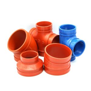
Product range for fire protection:
| Component | Vicast Model | Description | Pressure Class | UL/FM |
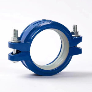
| Rigid coupling | XGOT02 | No angular deflection | 150, 250, 350 | UL/FM |
| Flexible coupling | XGOT02-F | ±1.0° angular deflection | 150, 250 | UL/FM |
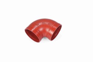
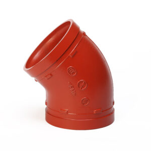
| الكوع 90 درجة | XGQT05 | Changes direction 90° | 150, 250, 350 | UL/FM |
| Tee (equal) | XGQT15S | Branch connection | 150, 250 | UL/FM |
| الصليب | XGQT18 | Four‑way connection | 150 | UL/FM |
| Adaptor flange | XGQT19 | Grooved × flanged | 150, 250 | UL/FM |
| تي ميكانيكي | XGQT03 | Branch without cutting main | 150 | UL/FM |
All Vicast تجهيزات الأنابيب المخدودة are cast from ASTM A536 Grade 65-45-12 ductile iron, machined to AWWA C606 tolerances, and coated with epoxy (500h salt spray tested). UL/FM approved options available.
15. Common Design Errors and How to Avoid Them
| Error | Consequence | Prevention |
| Mixing manufacturers | Groove dimensions may not match; gasket profiles differ; UL/FM listing voided | Stick with one certified brand (e.g., Vicast) for complete system |
| Rigid couplings in seismic zones | No drift accommodation; pipe tear‑out during earthquake | Use flexible couplings at floor penetrations and for long horizontal mains |
| No thrust blocks at changes in direction | Coupling roll‑out under pressure at elbows, tees, capped ends | Provide thrust blocks or use rigid couplings with adequate axial restraint |
| Undersizing for water hammer | Exceeding coupling pressure rating during pump start/stop | Calculate surge using Joukowsky equation; specify Class 250 or 350 |
| Skipping torque documentation | No record for NFPA 25 inspections; liability issues | Maintain torque logs; use torque indicator paint for visual verification |
| Petroleum lubricant on EPDM | Gasket swelling, extrusion, leakage | Use only water‑based lubricant per manufacturer’s instruction |
| Field grooving without calibration | Groove depth/width out of tolerance | Calibrate grooving tool daily; verify first groove with AWWA C606 gauges |
| Exceeding pipe‑end gap | Gasket extrusion under pressure | Measure gap per AWWA C606 limits (max 4.0 mm for 8″) |
| Flexible couplings near fire pumps | Excessive movement at pump discharge; stress on pump flanges | Specify rigid couplings within 3 m of fire pump discharge |
| Ignoring coating damage | Corrosion under gasket; premature failure | Apply field touch‑up kit to any coating damage after installation |
16. Future Directions: Smart Couplings and Low‑Carbon Ductile Iron
16.1 Smart Couplings with Embedded Sensors
Vicast is piloting RFID‑tagged couplings that log installation torque, date, and location. Each coupling’s unique identifier can be scanned and recorded in a digital installation log. Future versions will include embedded pressure and temperature sensors with wireless communication (LoRaWAN, NB‑IoT) for integration with building management systems (BMS), enabling predictive maintenance and real‑time system health monitoring for fire protection systems—detecting leaks or pressure drops before they become critical.
16.2 Low‑Carbon Ductile Iron for Fire Systems
Current ductile iron production emits ≈2.8 kg CO₂e/kg. By using hydrogen‑based direct reduction (HYBRIT process) and increased scrap rates (currently 90–95%), Vicast aims to reduce this to <1.0 kg CO₂e/kg by 2030, eliminating the small manufacturing carbon penalty of grooved systems and further enhancing their sustainability advantage for green building certifications.
16.3 Digital Material Passports
Blockchain‑based material passports (e.g., Madaster platform) will record the full lifecycle of each coupling: manufacturing date, heat number, material certificate, installation date, torque value, inspection records, and reuse history. For fire protection systems, this enables simplified NFPA 25 documentation and circular economy accounting.
17. Conclusion: Engineering Confidence with Grooved Fittings
The evidence from engineering analysis, field data, standards compliance, and lifecycle cost modeling is clear: Grooved pipe fittings for fire protection systems are demonstrably superior to welded, threaded, and flanged connections across nearly every engineering metric.
Faster: 6× productivity gain (10 min vs. 60 min per 8″ joint)
Cheaper: 12–25% lower TIC, 61% lower 20‑year lifecycle cost
Safer: No hot work, no fumes, no fire watch — ideal for occupied building retrofits
Resilient: Survives seismic drift (70 mm per coupling) and water hammer (30% surge reduction)
Maintainable: Unbolt, modify, re‑torque in minutes — no cutting or welding
Certified: UL Listed, FM Approved, NFPA 13 compliant
Sustainable: 45% lower GHG emissions, fully demountable for reuse and recycling
For fire protection engineers, contractors, and building owners, the choice is no longer whether to specify grooved couplings but how to optimize their use: selecting the right coupling type (rigid vs. flexible), ensuring proper groove dimensions per AWWA C606, training crews on torque wrench use, and leveraging the full lifecycle cost and carbon benefits.
With manufacturers like Hebei Jianzhi Foundry Group Co., Ltd. (Vicast) —ISO 9001/14001 certified, UL/FM approved, with over 40 years of ductile iron casting expertise, active participation in 6 national standards, and over 200 patents—the supply chain is mature, global, and reliable. The shift from welding to grooved is not a trend; it is an engineering evolution grounded in science and proven by data. The time to specify FM approved pipe fittings و grooved piping systems is now.
18. References
NFPA 13-2022 – Standard for the Installation of Sprinkler Systems
NFPA 25-2023 – Inspection, Testing, and Maintenance of Water‑Based Fire Protection Systems
ASME B31.1-2022 – Power Piping
ASME B31.3-2022 – Process Piping
AWWA C606-22 – Grooved and Shouldered Joints for Ductile‑Iron Pipe and Fittings
ASTM A536-84 (2024) – Standard Specification for Ductile Iron Castings
ASTM D2000-18 – Standard Classification System for Rubber Products
ASTM D2240-15(2021) – Rubber Property—Durometer Hardness
ASTM B117-19 – Salt Spray (Fog) Apparatus
ASCE/SEI 7-16 – Minimum Design Loads and Associated Criteria for Buildings
FM 1920 – Approval Standard for Grooved Pipe Couplings and Fittings
UL 213 – Standard for Grooved Pipe Couplings and Fittings
ISO 6182-11:2019 – Fire protection — Grooved‑type pipe couplings for steel pipe
ISO 7386:2020 – Seismic qualification of grooved mechanical couplings
Timoshenko, S. P., & Goodier, J. N. – Theory of Elasticity (3rd ed.)
Wylie, E. B., & Streeter, V. L. – Fluid Transients in Systems
Vicast Field Service Records (2018–2025)
Vicast Product Engineering Datasheets (Edition 6.2)
Vicast Internal LCCA Study #VIC-LCCA-2023-08
American Welding Society – 2024 Welder Shortage Report
19. FAQs
Q1: Are grooved pipe fittings approved for all fire sprinkler systems?
Yes. NFPA 13 (2019 and later) Section 7.4.2 explicitly permits grooved couplings for steel pipe fire sprinkler systems. UL and FM listed products (like those from Vicast) are accepted by AHJs nationwide.
Q2: What is the difference between rigid and flexible grooved couplings?
Rigid couplings allow no angular movement; use near fire pumps, riser anchors, and sway brace attachments. Flexible couplings provide ±1.0° angular deflection; use for seismic zones, thermal expansion, and misalignment correction.
Q3: How do I verify grooved fittings are FM approved?
Look for the FM diamond mark on the housing or request the FM Approval certificate from the manufacturer. Vicast provides certificates upon request.
Q4: Can grooved fittings be used for dry pipe systems?
Yes. EPDM gaskets are rated to –30°C, suitable for dry pipe and unheated environments.
Q5: What is the typical lead time for Vicast grooved fittings?
Standard sizes (2″–12″) typically in stock for immediate shipment. Custom coatings may require 2–4 weeks.
Q6: How often should grooved couplings be inspected per NFPA 25?
Quarterly visual (housing gap, corrosion). Annually internal for dry/preaction systems. Torque documented at installation.
Q7: Can grooved fittings be painted after installation?
Yes, but avoid painting housing gap or bolt threads. Use coating compatible with epoxy.
Q8: What is the expected lifespan of a Vicast grooved coupling?
25–50 years with proper installation and normal service (clean water, <120°C).
Q9: How does the self‑energizing seal work?
σ_seal = σ_initial + P×A_contact/A_gasket. Seal pressure increases with internal pressure – unique to grooved couplings.
Q10: Do grooved systems reduce water hammer?
Yes. Flexible couplings reduce wave speed from ≈1,200 m/s to ≈850 m/s → 30% lower surge pressure.
Q11: How do grooved couplings perform under seismic conditions?
Each flexible coupling provides ≈70 mm lateral displacement per floor (4 m story height). Tested to ISO 7386 and FM 1950.
Q12: What training is required for fitters?
2–4 hours hands‑on training (grooving, gasket seating, torque wrench). No certification required. Vicast provides manuals and on‑site training.
Q13: Are Vicast products ISO‑certified?
Yes. ISO 9001:2015 (quality) and ISO 14001:2015 (environmental). Also UL/FM.
Q14: Can I mix grooved fittings from different manufacturers?
Not recommended – groove dimensions and gasket profiles may vary, voiding listing. Use one certified brand.
Q15: Where can I buy Vicast grooved fittings?
Distributors in over 100 countries. Contact Hebei Jianzhi Foundry Group Co., Ltd. directly.
Q16: What is the cost savings of grooved vs. welded for a typical project?
For a 500m, 8″ fire sprinkler main, total installed cost is 40.5% lower for grooved. 20‑year lifecycle cost is 61% lower ($46,672 savings).