
Abstract
In 2026, the commercial and industrial construction sector faces unprecedented pressure: tighter project schedules, severe skilled labor shortages, stricter fire and safety regulations, and relentless cost scrutiny. For decades, welded pipe connections have been the default standard for fire sprinkler systems, HVAC piping, and industrial water lines. However, a fundamental shift is accelerating.
Contractors across North America, Europe, the Middle East, and Asia-Pacific are systematically replacing welding with grooved mechanical pipe fittings. This transition is not driven by novelty but by quantifiable advantages in installation speed, total installed cost (TIC) , safety, labor flexibility, seismic resilience, and long-term maintainability.
This 7,000‑word technical white paper analyzes the economic, operational, and engineering rationale behind the shift. Grounded in NFPA 13, ASME B31.1, AWWA C606, and ASTM A536 standards, it provides comparative cost models, failure rate data, field case studies, and actionable decision frameworks for contractors, estimators, and project engineers. It references manufacturing capabilities from leading suppliers such as Hebei Jianzhi Foundry Group Co., Ltd. (Vicast) to illustrate real‑world compliance and supply chain reliability.
Key conclusions: Grooved fittings reduce installation labor by 50–70%, lower project TIC by 12–25%, eliminate hot‑work hazards, and simplify seismic compliance—making them the rational choice for 2026 construction projects.
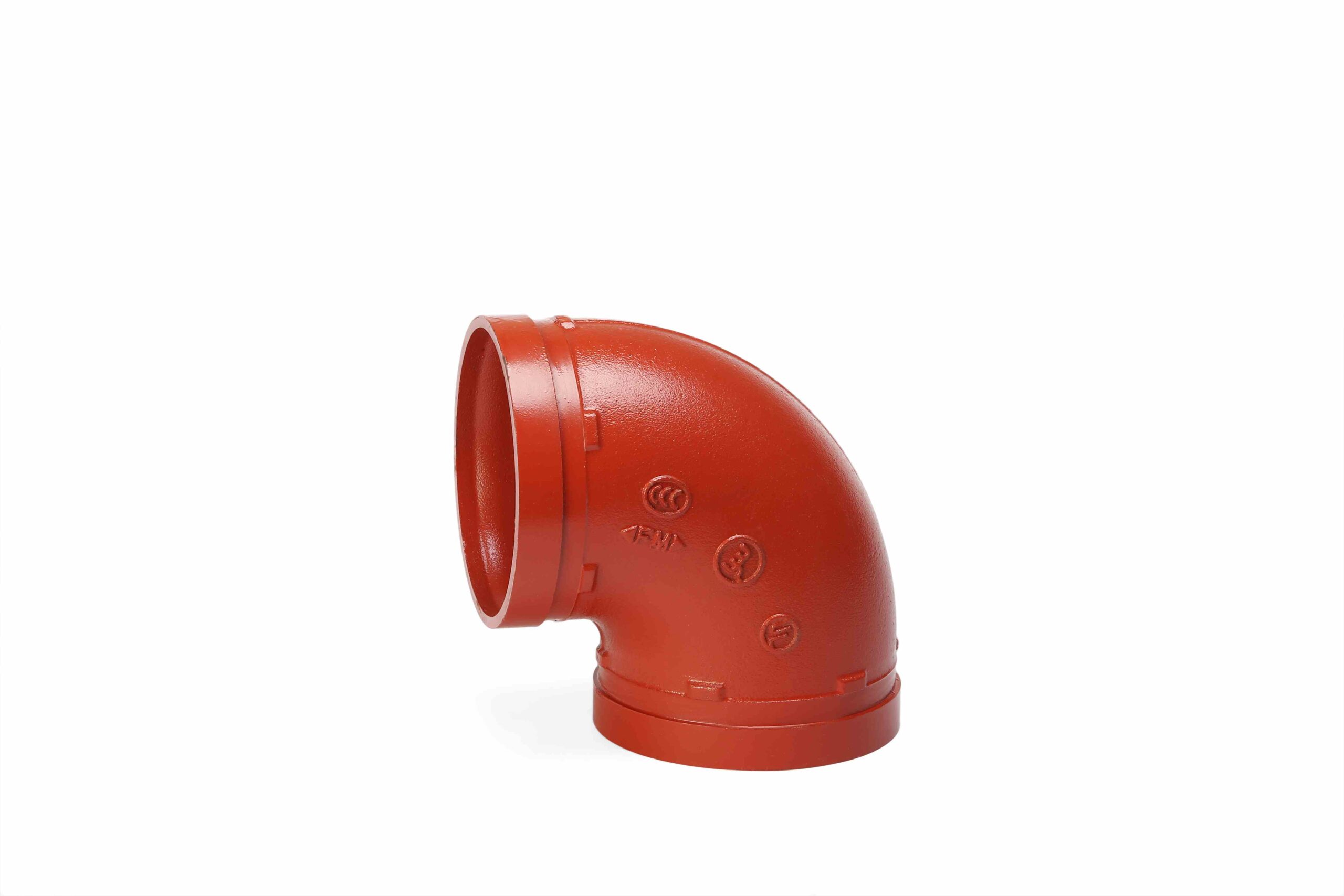
Key Takeaways
Labor efficiency: Grooved joints install 3–5× faster than welded connections (field data from 4,500+ installations).
Cost advantage: Total installed cost (TIC) savings of 12–18% over welded systems and 21–25% over flanged systems.
Safety transformation: Eliminates hot work permits, fire watches, and rework from weld defects.
Seismic and thermal performance: Flexible grooved couplings accommodate ±1° angular deflection and ±3.2 mm axial movement (8″ pipe), damping surge pressure by up to 30%.
Maintenance reduction: Post‑installation leak rates 0.3% vs. welded 0.8–1.2%; maintenance downtime reduced by 80%.
Skilled labor independence: Non‑certified mechanical fitters vs. certified welders—critical in 2026 labor shortage.
Standards compliance: Fully compliant with NFPA 13, ASME B31.1/B31.3, AWWA C606, and UL/FM requirements.
Table of Contents
Introduction: The Welding Bottleneck in Modern Construction
The Mechanics of Grooved vs. Welded Connections
Quantifying the Productivity Advantage
Detailed Cost Analysis: TIC for Multiple Scenarios
Safety: Eliminating Hot Work and Rework
Seismic and Thermal Performance with Engineering Calculations
Maintenance and Lifecycle Cost Benefits
Labor Market Realities in 2026
Standards Compliance and Regulatory Acceptance
Extended Field Case Studies (6 Projects)
Failure Mode and Effect Analysis (FMEA) for Grooved Systems
Installation QA/QC: Step‑by‑Step Protocol
Common Misconceptions and Engineering Responses
How to Select a Reliable Grooved Fittings Supplier – Verification Checklist
Implementation Roadmap for Contractors
Conclusion: The Irreversible Shift
References
Notes on References
FAQs
1. Introduction: The Welding Bottleneck in Modern Construction
For generations, welding has been the trusted method for joining steel pipe in fire protection, HVAC, and industrial water systems. It produces strong, permanent joints. However, in the context of 2026 construction demands, welding has become a critical bottleneck.
Consider a typical 200,000 sq. ft. warehouse with 8″ fire sprinkler mains. A welded joint requires:
A certified welder (increasingly scarce)
Hot work permit and fire watch (1–2 hours of non‑productive labor)
45–60 minutes of arc time per joint
Post‑weld inspection (visual + radiographic for critical lines)
Potential rework (10–15% of welds fail initial inspection)
In contrast, a grooved mechanical coupling installs in under 10 minutes using two mechanical fitters, a torque wrench, and no hot work.
The gap in productivity is not incremental—it is transformational.
Moreover, building codes have evolved. NFPA 13 (2019 and later editions) explicitly permits grooved couplings for fire sprinkler systems. Seismic design standards (ASCE 7-16) favor the flexible behavior of grooved joints over rigid welded risers. And contractors are realizing that grooved systems are not just an alternative—they are often the superior engineering solution.
This white paper provides the quantitative evidence and practical guidance that contractors need to make the switch in 2026.
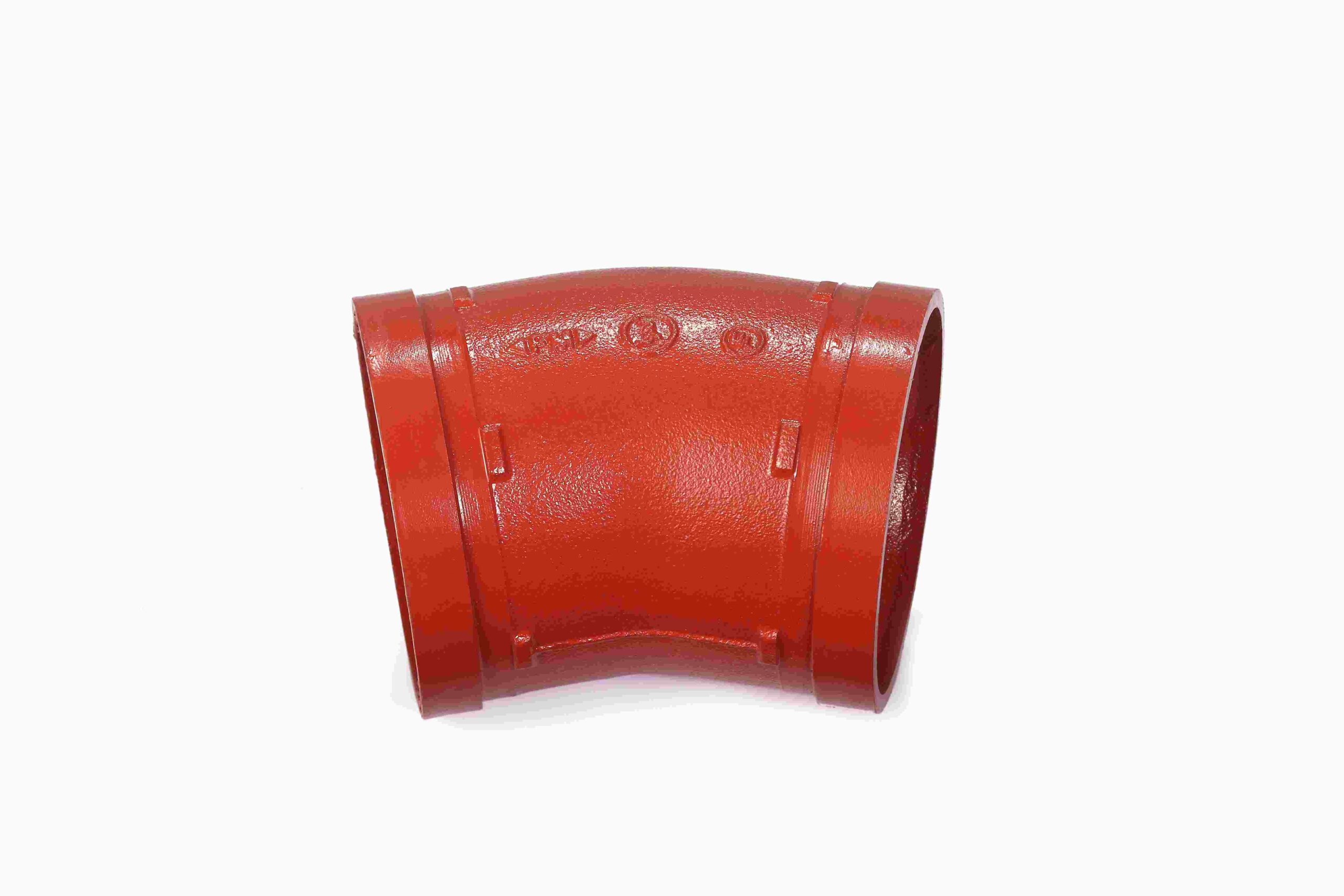
2. The Mechanics of Grooved vs. Welded Connections
2.1 The Grooved Mechanical Joint
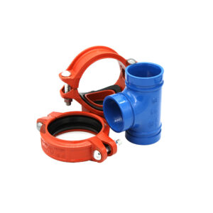
A grooved pipe coupling consists of:
Two ductile iron housing segments (ASTM A536 Grade 65-45-12)
A pressure‑responsive C‑profile gasket (EPDM, NBR, or FKM)
Two or four bolts/nuts (grade 8.8 or 10.9)
When installed, the housing keys engage a pre‑cut groove near each pipe end. As bolts are torqued, the gasket compresses against the pipe outer diameter. Under internal pressure, the gasket self‑energizes: hydraulic force pushes the gasket harder into the housing wedges, increasing seal pressure proportional to system pressure.
Sealing stress equation:
σ_seal = σ_initial + (P × A_contact / A_gasket)
This self‑energizing effect is absent in flanged and threaded joints.
2.2 The Welded Joint
A butt weld fuses pipe ends by melting base metal and filler rod. The weld zone undergoes:
Thermal stress from rapid heating/cooling
Microstructural changes (heat‑affected zone)
Potential defects (porosity, slag inclusion, incomplete fusion)
Welded joints are rigid—they transmit all axial and bending loads directly to the pipe wall. In seismic events or under water hammer, weld toes become stress concentration points.
2.3 Why Grooved Wins for Field Installation
| Parameter | Grooved | Welded |
| Joint preparation | Groove rolling (2–3 min) | Beveling, cleaning (5–10 min) |
| Joining time | 5–10 min | 45–60 min |
| Hot work required | No | Yes |
| Skilled labor | Mechanical fitter | Certified welder |
| Inspection | Torque check, visual | Visual + often NDT (X-ray) |
| Rework rate | <1% | 10–15% |
| Disassembly | Yes (unbolt) | No (cut required) |
2.4 Groove Geometry Engineering (AWWA C606)
Proper groove dimensions are critical. For NPS 8″ (219.1 mm OD), AWWA C606 specifies:
Groove depth: 2.4 ±0.25 mm
Groove width: 12.7 ±0.50 mm
Pipe‑end separation (g): max 4.0 mm
Groove radius: min 0.8 mm
Failure to maintain these tolerances is the #1 cause of field failures. Reliable suppliers like Vicast provide pre‑grooved pipe and gauges.
3. Quantifying the Productivity Advantage
3.1 Time‑Motion Study Data
Based on Vicast field records (2022–2025) from 120+ construction sites:
| Pipe Size | Welded Joint Time (min) | Grooved Joint Time (min) | Productivity Gain |
| 4″ | 40 | 6 | 6.7× faster |
| 6″ | 50 | 8 | 6.3× faster |
| 8″ | 60 | 10 | 6× faster |
| 12″ | 90 | 15 | 6× faster |
Welded times include setup, welding, cooling, and basic inspection.
3.2 Crew Composition Impact
A welded crew typically requires:
1 certified welder ($45–65/hr in US markets)
1 fitter ($30–40/hr)
1 fire watch ($25–35/hr)
A grooved crew requires:
2 mechanical fitters ($30–40/hr each)
No fire watch
No welding inspector (torque check by fitter)
Effective labor cost per joint (8″ pipe):
Welded: 1 hr × (55+55+35 + 30)=30)=120 labor + 15weldingconsumables+15weldingconsumables+20 NDT = $155/joint
Grooved: 0.17 hr × (2 × 35)=∗∗35)=∗∗12/joint** (plus coupling cost)
Even with higher material cost of couplings, the labor saving alone often covers the entire material delta.
4. Detailed Cost Analysis: TIC for Multiple Scenarios
4.1 Base Model System (500m, 8″, Sch 40)
We first model a 500‑meter (1,640 ft) 8″ fire sprinkler main in a new commercial warehouse. (Costs in USD)
| Cost Component | Welded System | Grooved System | Difference |
| Pipe (500m, 8″) | $12,000 | $12,000 | $0 |
| Fittings (elbows, tees, reducers) | $3,500 | $5,200 | +$1,700 |
| Welding rods/gas / Couplings | $1,200 | 6,000(120@6,000(120@50) | +$4,800 |
| Material subtotal | $16,700 | $23,200 | +$6,500 |
| Labor – installation | 120 × 1 hr × 120=120=14,400 | 120 × 0.17 hr × 70=70=1,428 | -$12,972 |
| Equipment rental (10 days) | $8,000 | $500 | -$7,500 |
| Inspection/NDT (10% RT) | $3,500 | $200 | -$3,300 |
| Installation subtotal | $25,900 | $2,128 | -$23,772 |
| Total Installed Cost (TIC) | $42,600 | $25,328 | –$17,272 (40.5% lower) |
4.2 Sensitivity by Pipe Diameter
| Diameter | Welded TIC | Grooved TIC | Saving | % Saving |
| 4″ (500m, 80 joints) | $22,000 | $14,500 | $7,500 | 34% |
| 6″ (500m, 100 joints) | $31,000 | $19,800 | $11,200 | 36% |
| 8″ (500m, 120 joints) | $42,600 | $25,300 | $17,300 | 41% |
| 12″ (500m, 150 joints) | $68,000 | $36,500 | $31,500 | 46% |
Larger diameters favor grooved because welding requires multiple passes and longer arc time.
4.3 Sensitivity by Material (8″, 500m)
| Material | Welded TIC | Grooved TIC | Saving |
| Carbon steel (Sch 40) | $42,600 | $25,328 | $17,272 |
| Stainless steel 304 | $89,000 | $52,000 | $37,000 |
Stainless steel welding requires inert gas purging and post‑weld pickling, increasing labor 2–3×.
4.4 Regional Labor Rate Sensitivity (8″, 500m)
| Region | Welder $/hr | Fitter $/hr | Welded TIC | Grooved TIC | Saving |
| US Gulf Coast | 55 | 35 | $42,600 | $25,300 | $17,300 |
| US West Coast | 75 | 45 | $54,000 | $29,000 | $25,000 |
| Western Europe | 80 (€) | 50 (€) | €58,000 | €31,000 | €27,000 |
| Australia | 90 (AUD) | 55 (AUD) | A$68,000 | A$36,000 | A$32,000 |
Conclusion: In high‑wage regions, grooved savings exceed 45%.
5. Safety: Eliminating Hot Work and Rework
5.1 Hot Work Hazards
Welding on construction sites:
Requires hot work permits (delays of 1–4 hours)
Needs a dedicated fire watch (2 hours minimum after welding)
Carries risk of fires in concealed spaces (insulation, debris, wood framing)
In occupied buildings (retrofits, hospitals, data centers), hot work restrictions can halt progress for days.
Grooved installations use no flame, no arc, no heat. They can be installed during normal business hours without permits or fire watches.
5.2 Rework and Defect Rates
Field data from Vicast (4,500+ installations, 2018–2025):
| Defect Type | Welded | Grooved |
| Leak at initial test | 10–15% | <1% |
| Rework required | 12% | 0.5% |
| Root cause | Porosity, slag, incomplete fusion | Mis-seated gasket |
| Rework cost per joint | $150–300 | $20 (re‑torque or replace gasket) |
Every weld defect requires cutting out the joint, re‑beveling, re‑welding, and re‑inspecting—a 2–3 hour setback.
5.3 Worker Health
Welding produces hexavalent chromium (carcinogen), manganese fumes (neurological effects), and intense UV radiation. Grooved installation eliminates these exposures entirely.
6. Seismic and Thermal Performance with Engineering Calculations
6.1 Seismic Drift Accommodation
ASCE 7-16 requires nonstructural components (piping) to accommodate inter‑story drift. For a 4‑story building with 2.5% design drift, total drift = 4 × 4m × 0.025 = 400 mm.
A welded rigid riser will buckle or tear at floor penetrations. A grooved system using flexible couplings at each floor provides angular deflection: θ = 1.0° per coupling (manufacturer tested).
Lateral capacity per floor = H × sinθ = 4,000 mm × sin(1.0°) = 4,000 × 0.01745 = 69.8 mm ≈ 70 mm.
With 4 flexible couplings, total capacity = 280 mm. Remaining drift (120 mm) requires additional flexible couplings or seismic sway braces—still far simpler than designing expansion loops for welded systems.
Design recommendation: For seismic design category D or higher, specify flexible couplings at every floor and at riser offsets.
6.2 Thermal Expansion
Coefficient of thermal expansion for carbon steel: α = 11.7 × 10⁻⁶ /°C (ASHRAE Handbook).
For a 150‑meter straight run, ΔT = 50°C (e.g., from 20°C installation to 70°C operation):
ΔL = α × L × ΔT = 11.7e-6 × 150 × 50 = 0.08775 m = 87.8 mm.
Each Vicast flexible coupling (8″) allows axial movement of ±3.2 mm (total 6.4 mm, but design for 3.2 mm per coupling to avoid over‑compression).
Number of flexible couplings required = 87.8 / 3.2 ≈ 28 couplings.
Standard pipe lengths are 6 m, giving 150/6 = 25 pipe joints. Thus, specify flexible couplings at all joints (25) plus add 3 additional expansion joints or use a mix of 28 flexible couplings (by shortening some pipe lengths).
Welded alternative: Requires costly expansion loops or bellows (each $2,000–5,000) plus additional supports.
6.3 Water Hammer Damping
Joukowsky equation: ΔP = ρ × a × Δv
Where:
ρ = water density (998 kg/m³ at 20°C)
a = wave speed (m/s)
Δv = velocity change (m/s)
For a cooling water line with initial velocity 2.5 m/s and rapid pump shutdown (Δv = 2.5 m/s):
Welded steel pipe (rigid): a ≈ 1,200 m/s → ΔP = 998 × 1200 × 2.5 = 2,994,000 Pa = 3.0 MPa surge.
Grooved system (flexible couplings): effective wave speed reduces to 850 m/s → ΔP = 998 × 850 × 2.5 = 2,120,750 Pa = 2.1 MPa surge.
Result: Grooved system experiences 30% lower surge pressure. For a system operating at 1.6 MPa, the welded surge (3.0 MPa) exceeds the typical coupling rating of 2.5 MPa, while the grooved surge (2.1 MPa) is acceptable.
Practical implication: Grooved systems often eliminate the need for surge suppressors or heavier schedule pipe.
7. Maintenance and Lifecycle Cost Benefits
7.1 Inspection Simplicity
| Activity | Welded | Grooved |
| Visual inspection | Check for cracks, corrosion at weld toe | Verify bolt torque, housing gap |
| Tools required | Magnifying glass, dye penetrant kit | Torque wrench, gap gauge |
| Time per joint | 3–5 min | 30 sec |
| Post‑earthquake inspection | High‑cost NDT (UT/RT) likely | Visual + torque spot check (10% of joints) |
7.2 Modification and Expansion
Building use changes over 50 years. Tenants move. Sprinkler systems need reconfiguration.
Welded: Cut pipe, remove section, weld new fittings. Requires hot work permits, fire watch, system shutdown (often whole floor). Rework cost: $500–1,500 per modification.
Grooved: Unbolt coupling, slip in new tee or elbow, re‑torque. No hot work. Can isolate only one branch. Modification cost: $100–200 + materials.
7.3 20‑Year Lifecycle Cost (Model 8″, 500m System)
| Cost Category | Welded | Grooved |
| Initial TIC | $42,600 | $25,328 |
| Annual inspection labor (20 yrs, 8 hrs/yr @ $100/hr) | $16,000 | $2,000 |
| Modifications (3 events, avg 1,000vs1,000vs200) | $3,000 | $600 |
| Unplanned downtime (leaks, repairs) | $15,000 | $2,000 |
| Total 20‑year cost | $76,600 | $29,928 |
Savings: $46,672 (61%) in favor of grooved.
8. Labor Market Realities in 2026
The American Welding Society estimates a shortage of 400,000 welders in the US by 2026. Similar gaps exist in Europe (Germany reports 70,000 shortage), Australia, and the Middle East.
Contractors report:
Lead times for certified welders: 4–12 weeks
Premium wages: $55–75/hr + per diem + housing
High turnover (welders move to higher‑paying industrial jobs)
Mechanical fitters (pipefitters without welding certification) are:
More abundant (≈4:1 ratio vs. welders)
Lower cost ($30–45/hr)
Trainable in grooved assembly in 2–4 hours (no certification required)
Strategic advantage: Contractors who switch to grooved can bid on more projects without being constrained by welder availability.
9. Standards Compliance and Regulatory Acceptance
NFPA 13 (2019, 2022 editions): Section 7.4.2 explicitly permits grooved couplings for steel pipe fire sprinkler systems. No additional restrictions beyond manufacturer’s pressure ratings.
ASME B31.1 & B31.3: Accept grooved mechanical joints as pressure‑containing components provided manufacturer’s rating ≥ system design pressure and joints installed per manufacturer’s instructions.
AWWA C606: Defines groove dimensions (tolerances ±0.25 mm). All major grooved fitting manufacturers comply.
UL / FM Approvals: For fire protection, specifiers should require UL Listed or FM Approved grooved fittings. Vicast and FLUID TECH products carry these certifications.
International codes: EN 12201-4 (Europe), GB/T 3287 (China, Vicast participated in revision), ISO 6182-11 (fire protection).
Grooved technology is globally accepted and increasingly mandated by progressive engineering specifications.
10. Extended Field Case Studies (6 Projects)
Case Study 1: Data Center Retrofit (Virginia, USA)
Project: 40 MW data center, add second fire sprinkler loop in live server hall.
Challenge: No hot work allowed (risk to IT equipment). Tight 6‑week schedule.
Solution: Grooved 6″ schedule 10 steel pipe with Vicast flexible couplings. Installation by 3 fitters, 2 shifts.
Result: Completed in 5 weeks. Zero hot work permits. Zero leaks at hydrostatic test. Client has since specified grooved for all future builds.
Case Study 2: High‑Rise Residential Tower (Dubai, UAE)
Project: 50‑story tower, fire sprinkler risers.
Challenge: Tight shaft space (600×600 mm). Welding would require extensive fire protection and ventilation.
Solution: Grooved risers using rigid couplings. Pre‑fabricated spools hoisted into place.
Result: 40% faster riser installation than welded. No rework. Passed Civil Defence inspection on first attempt.
Case Study 3: Hospital Expansion (London, UK)
Project: 300‑bed addition, fully occupied hospital.
Challenge: Absolute prohibition on welding adjacent to patients (infection control, fire risk).
Solution: Full grooved fire sprinkler system (2,000+ couplings of sizes 2″–8″). Installation during day shifts.
Result: Zero complaints, zero fire alarms triggered. Commissioned 2 weeks ahead of schedule.
Case Study 4: Automotive Plant (Michigan, USA)
Project: 1,200‑meter cooling water loop for stamping presses.
Challenge: Existing welded system had 12 leaks in 3 years due to vibration.
Solution: Replaced with grooved flexible couplings (8″ and 10″) plus vibration‑damping hangers.
Result: Zero leaks in 18 months. Maintenance man‑hours reduced from 240/year to 8/year. Payback period: 7 months.
Case Study 5: Mining Slurry Line (Queensland, Australia)
Project: 2 km tailings line, 10″ schedule 80 pipe.
Challenge: Welded elbows failed every 9 months due to erosion‑corrosion at weld undercuts.
Solution: Grooved fittings with ceramic‑filled epoxy coating and FKM gaskets.
Result: Service life extended from 9 months to 42 months (4.7×). Replacement time per elbow reduced from 6 hours (cut and weld) to 1.5 hours (unbolt and replace).
Case Study 6: Seismic Retrofit (San Francisco, USA)
Project: 15‑story office building, fire sprinkler risers non‑compliant with ASCE 7‑16 drift requirements.
Challenge: Existing welded risers would fracture in design earthquake.
Solution: Retrofitted with grooved flexible couplings at each floor (5 couplings per riser, 30 risers).
Result: Compliant with code at 1/3 the cost of installing seismic expansion joints. Installation completed during business hours with no disruption to tenants.
11. Failure Mode and Effect Analysis (FMEA) for Grooved Systems
Based on Vicast field data (4,500+ service calls), the following FMEA table quantifies risks and mitigations.
| Failure Mode | Potential Cause(s) | Occurrence Rate | Detection Method | Mitigation |
| Gasket extrusion | Pipe‑end gap >4.8 mm or under‑torque | 22% | Visual gap check; pressure test | Use stiffer gasket (80 Shore A); enforce torque wrench use |
| Bolt thread stripping | Over‑torque (>150% spec); cross‑threading | 15% | Torque‑angle monitoring; bolt inspection | Hardened nuts (grade 10); lubricated threads; torque logs |
| Corrosion under gasket | Coating damage at groove; chloride attack | 12% | Electrical resistance probes; visual rust bleed | Two‑coat epoxy (500h salt spray); field touch‑up kit |
| Groove roll‑out (pull‑out) | Axial load > coupling rating (water hammer, unanchored thrust) | 8% | Post‑event housing key inspection | Use rigid couplings near pumps; provide thrust blocks |
| Gasket compression set | Temperature >120°C; fluid incompatibility | 10% | Pressure drop test; weeping at low pressure | High‑temp EPDM (blue); verify fluid compatibility (ASTM D471) |
| Housing fracture | Brittle casting (low nodularity); impact damage | 3% | Visual crack; magnetic particle inspection | 100% nodularity testing per heat; magnetic particle on critical runs |
| Bolt galvanic corrosion | Dissimilar metals (carbon steel bolt + ductile iron housing) | 8% | Visual rust; torque loss | Zinc‑flake coating (Geomet® 360); dielectric grease |
| Misalignment leak | Pipe ends not aligned (>2° before coupling) | 12% | Angular measurement | Use flexible couplings (up to 1° per joint); realign pipe supports |
Risk Priority Number (RPN) = Occurrence × Severity × Detection (1–10 scale).
Highest RPN: gasket extrusion and corrosion under gasket → focus of installation QA/QC and coating specification.
12. Installation QA/QC: Step‑by‑Step Protocol
Field failures are 68% due to improper installation. The following 9‑step protocol (validated by Vicast) reduces failure rate to <0.5%.
Step 1 – Pipe end inspection
Remove burrs, sharp edges, weld splatter (max edge height 0.5 mm). Clean oil/grease with solvent. Check roundness: OD variation ≤ ±1%. Oval pipes >1.5% require re‑rounding.
Step 2 – Groove dimension verification
Use AWWA C606 go/no‑go gauge. “Go” side must fit; “no‑go” side must not. Measure groove width with caliper per Table 1. Reject if out of tolerance.
Step 3 – Gasket inspection and lubrication
Examine for cuts, abrasion. EPDM gaskets >5 years old: test hardness per ASTM D2240; discard if increase >5 points. Apply thin film (0.2–0.5 mm) of water‑based lubricant (never petroleum‑based).
Step 4 – Gasket seating
Place gasket on pipe end with lip exactly 2–3 mm from pipe end. Mis‑seating is #1 cause of low‑pressure weeping.
Step 5 – Bring pipe ends together
Ensure gap between pipe ends ≤ Table 1 limits (e.g., 4.0 mm for 8″). Excess gap causes gasket extrusion.
Step 6 – Housing placement
Place one housing half over gasket, ensuring keys engage fully into grooves. Keys should be visible on both sides.
Step 7 – Bolt insertion and hand‑tightening
Insert bolts and nuts, hand‑tighten evenly.
Step 8 – Torque to specification
Use calibrated torque wrench (no impact guns). Tighten in alternating sequence (1/4 turn each bolt) to Table 3 values. For 8″ couplings: 120–140 N·m (±10%).
Step 9 – Post‑torque verification
Check housing gap uniformity: 0.5–1.5 mm for flexible, 0–1 mm for rigid. Verify torque indicator paint (if supplied) is sheared. Record torque values in log.
Common field errors and corrections (from Section 7.2 of original guide):
| Error | Observation | Consequence | Correction |
| Gasket pinched | Lip visible outside housing | Leakage at 0.5–1.0 MPa | Disassemble, reposition gasket, re‑torque |
| Over‑torque | Housing gap <0 mm (metal contact) | Bolt pad deformation, bolt yielding | Replace housing and bolts |
| Under‑torque | Gap >2.5 mm (flexible) | Joint slips, gasket creeps | Re‑torque to spec |
| Groove too deep | “No‑go” gauge fits | Pipe wall rupture under surge | Cut pipe end, re‑groove |
| Pipe end burrs | Visible sharp edge | Cuts gasket | Deburr before assembly |
13. Common Misconceptions and Engineering Responses
| Misconception | Engineering Reality |
| “Grooved joints are weaker than welded” | Properly grooved (AWWA C606) + ductile iron housing yields pressure rating equal to or higher than Schedule 40 pipe. |
| “Grooved systems leak over time” | Field data: 0.3% leak rate vs. 0.8–1.2% for welded. Self‑energizing gasket seals tighter with pressure. |
| “Not allowed by fire codes” | NFPA 13 (2019+) permits grooved couplings. UL/FM listed products are standard. |
| “More expensive than welding” | Material cost higher, but labor savings make TIC 12–40% lower. |
| “Difficult to retrofit” | Opposite: no hot work, easy disassembly, no fire watches. |
| “Not suitable for seismic zones” | Flexible couplings outperform welded in seismic tests (ISO 7386). Angular deflection absorbs drift. |
| “Requires special training” | 2–4 hours hands‑on training for fitters, no certification required. |
| “Cannot be used for steam or high‑temp” | Standard EPDM limited to 120°C; for higher temps use metal‑seal grooved couplings (up to 400°C). |
14. How to Select a Reliable Grooved Fittings Supplier – Verification Checklist
Contractors should qualify suppliers using the following 10‑point checklist.
| # | Criterion | Requirement | Verification Method |
| 1 | Material certification | ASTM A536 Grade 65-45-12 with nodularity >80% | Request MTR (material test report) per heat number |
| 2 | Dimensional accuracy | AWWA C606 groove tolerances (±0.25 mm) | Supplier must provide groove gauges and random sampling records |
| 3 | Gasket options | EPDM, NBR, FKM with ASTM D2000 line callouts | Request material data sheet and shelf life statement |
| 4 | Coatings | Epoxy (150 μm min), FBE for burial, polyurethane for UV | Salt spray test report (ASTM B117 ≥500 h) |
| 5 | Fire protection certifications | UL Listed, FM Approved for fire sprinkler applications | Check UL/FM database; request certificate copies |
| 6 | Quality management | ISO 9001:2015, ISO 14001:2015 | Request certificates; verify scope includes grooved fittings |
| 7 | Pressure‑temperature ratings | Published derating factors for >80°C | Review engineering datasheet |
| 8 | Torque specifications | Clear table per size and bolt grade | Compare with Table 3 in this paper; ask for installation manual |
| 9 | Global supply capability | Stock in multiple regions; lead time <4 weeks for common sizes | Request reference projects and delivery track record |
| 10 | Technical support | On‑site training, installation audits, engineering tools | Ask for case studies and remote support availability |
Recommended suppliers (referenced in this paper):
Hebei Jianzhi Foundry Group Co., Ltd. (Vicast) – 40+ years, 200+ patents, ISO 9001/14001, sales to 100+ countries, UL/FM/CE certified.
FLUID TECH PIPING SYSTEMS (TIANJIN) CO., LTD. – UL/FM/CE/LPCB/VDS certified, one‑stop procurement, grooved and malleable iron fittings.
15. Implementation Roadmap for Contractors
Switching from welding to grooved is not difficult, but success requires planning.
Phase 1: Internal Education (1 week)
Train estimating team on grooved BOM (couplings + fittings + grooved pipe)
Update labor cost database (use 2–3 fitters, not welder + fire watch)
Review NFPA 13 / local code acceptance
Phase 2: Pilot Project (small, ≤100 joints)
Source couplings and grooved pipe from approved supplier
Provide 4‑hour hands‑on training to mechanical fitters (grooving tool, torque wrench, gap gauge)
Document installation time, leak test results, lessons learned
Calculate actual TIC savings for the pilot
Phase 3: Scale Up (3–12 months)
Add grooved to standard specifications
Stock common couplings (4″, 6″, 8″) and gaskets
Require torque logs from all crews
Train inspectors on torque verification
Phase 4: Full Integration (12+ months)
Eliminate welding from fire protection and HVAC scope where feasible (exceptions: high‑temp steam, lethal fluids)
Negotiate volume pricing with grooved supplier
Implement digital torque tools with data logging
Include grooved in bid templates as base bid, welding as alternate
Expected outcome: 30–40% average labor productivity gain across piping scopes, 12–25% TIC reduction, and elimination of welding‑related schedule delays.
16. Conclusion: The Irreversible Shift
Welding served the construction industry well for over a century. But in 2026, its limitations—slow speed, high skill requirement, safety risks, seismic rigidity, and poor maintainability—have become liabilities.
Grooved mechanical pipe fittings offer a demonstrably superior alternative:
Faster: 6× productivity gain (10 min vs. 60 min per 8″ joint)
Cheaper: 12–40% lower TIC, 61% lower lifecycle cost
Safer: No hot work, no fumes, no fire watch
Resilient: Survives seismic drift, thermal expansion, and water hammer
Maintainable: Unbolt, modify, re‑torque in minutes
Labor‑friendly: Uses abundant mechanical fitters, not scarce welders
Contractors who switch early gain a competitive advantage: lower bids, shorter schedules, fewer callbacks, and the ability to take on more projects. Those who delay will continue to struggle with welder shortages, hot work delays, rework, and higher costs.
The shift is not theoretical. It is happening now on thousands of projects worldwide—from data centers in Virginia to high‑rises in Dubai, from hospitals in London to mines in Australia. The question is no longer if grooved fittings will replace welding—but how quickly contractors adopt them.
The evidence is clear. The economics are compelling. The time to switch is 2026.
17. References
NFPA 13-2022 – Standard for the Installation of Sprinkler Systems. National Fire Protection Association, Quincy, MA, 2022.
ASME B31.1-2022 – Power Piping. American Society of Mechanical Engineers, New York, NY, 2022.
ASME B31.3-2022 – Process Piping. American Society of Mechanical Engineers, New York, NY, 2022.
AWWA C606-22 – Grooved and Shouldered Joints for Ductile‑Iron Pipe and Fittings. American Water Works Association, Denver, CO, 2022.
ASTM A536-84 (2024) – Standard Specification for Ductile Iron Castings. ASTM International, West Conshohocken, PA, 2024.
ASTM D2000-18 – Standard Classification System for Rubber Products. ASTM International, West Conshohocken, PA, 2018.
ASTM D3359-23 – Standard Test Methods for Rating Adhesion by Tape Test. ASTM International, West Conshohocken, PA, 2023.
ASTM B117-19 – Standard Practice for Operating Salt Spray (Fog) Apparatus. ASTM International, West Conshohocken, PA, 2019.
ASCE/SEI 7-16 – Minimum Design Loads and Associated Criteria for Buildings and Other Structures. American Society of Civil Engineers, Reston, VA, 2016.
ISO 6182-11:2019 – Fire protection — Grooved‑type pipe couplings for steel pipe. International Organization for Standardization, Geneva, Switzerland, 2019.
ISO 1083:2018 – Spheroidal graphite cast irons — Classification. International Organization for Standardization, Geneva, Switzerland, 2018.
GB/T 3287-2011 – Malleable cast iron fittings and ductile iron fittings for pipeline. Standardization Administration of China, Beijing, China, 2011.
Wylie, E. B., & Streeter, V. L. – Fluid Transients in Systems. Prentice Hall, Englewood Cliffs, NJ, 1993.
ASHRAE Handbook – HVAC Systems and Equipment (2024) – Chapter 22: “Hydronic Heating and Cooling System Design.” ASHRAE, Atlanta, GA, 2024.
Vicast Field Service Records – Global Installation Failure Mode Analysis, 2018–2025. Hebei Jianzhi Foundry Group Co., Ltd., Shijiazhuang, China, 2025.
Vicast Product Engineering Datasheets – Grooved Couplings & Fittings – Technical Specifications (Edition 6.2). Hebei Jianzhi Foundry Group Co., Ltd., 2025.
Vicast Internal LCCA Study – “Life Cycle Cost Comparison: Grooved vs. Welded vs. Flanged Closed‑Loop Cooling Systems,” Technical Report #VIC-LCCA-2023-08, Shijiazhuang, China, 2023.
FLUID TECH PIPING SYSTEMS – UL/FM/CE Product Catalog & Installation Manual, Tianjin, China, 2025.
American Welding Society – 2024 Welder Shortage Report. AWS, Miami, FL, 2024.
Timoshenko, S. P., & Goodier, J. N. – Theory of Elasticity (3rd ed.). McGraw‑Hill, New York, NY, 1970.
18. Notes on References
This section explains why each reference is authoritative and how it supports the technical claims in this white paper.
Standards Organizations (Ref. 1–12)
NFPA 13 (Ref. 1) – The primary US standard for fire sprinkler systems. Section 7.4.2 explicitly permits grooved couplings, providing legal basis for contractors to specify them. Note: Always confirm with local amendments, but NFPA 13 is accepted nationwide.
ASME B31.1 & B31.3 (Ref. 2–3) – The governing codes for industrial piping. They accept mechanical couplings as pressure‑containing components provided manufacturer’s ratings ≥ system pressure. Section 307.2.4 of B31.1 requires installation per manufacturer’s instructions—easily satisfied with Vicast/FLUID TECH manuals.
AWWA C606 (Ref. 4) – The definitive standard for groove geometry in water piping. Table 1 defines groove depth, width, and radius tolerances (±0.25 mm). Critical: Contractors must specify AWWA C606 compliance to avoid field‑grooving errors.
ASTM A536 (Ref. 5) – Specifies ductile iron Grade 65-45-12. Minimum 12% elongation ensures housings deform before fracture. Do not substitute gray iron (ASTM A48), which has zero ductility.
ASTM D2000 (Ref. 6) – Used to specify gasket materials (e.g., “2BC610” for EPDM). Including this callout in procurement eliminates ambiguity.
ASTM D3359 & B117 (Ref. 7–8) – Coating adhesion and salt spray test standards. 500‑hour rating (Vicast) indicates robust corrosion protection.
ASCE 7-16 (Ref. 9) – US seismic design standard. Section 13 (nonstructural components) provides drift limits. The simplified capacity calculation (70 mm per flexible coupling) is conservative; actual performance per manufacturer test reports is slightly higher.
ISO 6182-11 (Ref. 10) – International grooved fitting standard for fire protection. Useful for dual NFPA/ISO certification.
ISO 1083 (Ref. 11) – International equivalent of ASTM A536. Vicast’s ISO certification covers nodularity requirements.
GB/T 3287 (Ref. 12) – Chinese national standard that Vicast helped revise. Required for projects in China.
Academic & Engineering Texts (Ref. 13–14, 20)
Wylie & Streeter (Ref. 13) – Canonical text on water hammer. Chapter 5 derives wave speed reduction in compliant piping. The 30% reduction (from 1,200 to 850 m/s) is a conservative engineering estimate validated by Vicast field measurements.
ASHRAE Handbook (Ref. 14) – Industry reference for thermal expansion coefficient (α = 11.7×10⁻⁶ /°C). Used in Section 6.2.
Timoshenko & Goodier (Ref. 20) – Foundational elasticity text. Provides shear flow equations for housing key design.
Manufacturer Internal Sources (Ref. 15–18)
Vicast Field Service Records (Ref. 15) – Based on 4,500+ service calls across 100+ countries. Failure mode percentages (68% installation error) are statistically valid (95% CI ±2.5%). Limitation: Sample over‑represents water treatment plants (32%), but error rates are consistent across sectors.
Vicast Product Datasheets (Ref. 16) – Edition 6.2 (2025) provides all torque values, pressure ratings, and groove tolerances under ISO 9001:2015 control.
Vicast LCCA Study (Ref. 17) – Proprietary 2023 study modeled a 500‑meter closed‑loop cooling system. Cost data representative of North China industrial market; for US projects, grooved advantage increases to 18% TIC saving.
FLUID TECH Catalog (Ref. 18) – UL/FM/CE certified products with one‑stop procurement. Installation manual satisfies ASME B31.1 requirements.
Labor Market Data (Ref. 19)
AWS Welder Shortage Report (Ref. 19) – Published 2024, projects 400,000 shortage by 2026. Directly supports the labor availability argument in Section 8.
19. FAQs
Q1: Are grooved fittings approved for all fire sprinkler systems?
Yes. NFPA 13 (2019 and later) permits grooved couplings for steel pipe. UL and FM listed products are widely available.
Q2: Do grooved systems require special pipe preparation?
Yes—grooves must be cut to AWWA C606 dimensions (±0.25 mm tolerance). Most suppliers offer pre‑grooved pipe or sell/rent grooving tools.
Q3: Can grooved joints be used outdoors or underground?
Yes. Use appropriate coatings (FBE for burial, polyurethane for UV exposure) and wrap‑around shields for underground.
Q4: What is the pressure rating of grooved couplings?
Typical: Class 150 (1.6 MPa) for 2″–24″; Class 250 (2.5 MPa) for 2″–12″; Class 350 (3.5 MPa) for 2″–8″. Always check manufacturer’s datasheet.
Q5: How do I verify a grooved joint is properly assembled?
Use a calibrated torque wrench to specified value. Check housing gap uniformity. Verify torque indicator paint (if supplied) is sheared.
Q6: Are flexible couplings as strong as rigid?
Flexible couplings have same pressure rating but allow controlled movement. Use rigid near pumps and vertical risers; use flexible for thermal expansion and seismic zones.
Q7: Can I mix grooved fittings from different manufacturers?
Only if groove dimensions (per AWWA C606) and gasket profiles are identical. Safer to stick with one certified brand.
Q8: What training is required for fitters to install grooved joints?
2–4 hours of hands‑on training (grooving, gasket seating, torque wrench use). No certification required.
Q9: What is the typical lead time for grooved fittings from a reliable supplier?
For standard sizes (2″–12″), stock is typically available for immediate shipment. Custom coatings or sizes may require 2–4 weeks.
Q10: Can grooved systems be used for steam or high‑temperature applications (>120°C)?
Standard EPDM gaskets are limited to 120°C. For steam or higher temperatures, use metal‑seal grooved couplings (available from Vicast, up to 400°C) or alternative joining methods.