Rigid coupling vs flexible coupling: which one to choose for fire sprinkler risers
Rigid vs flexible grooved coupling: which one to choose for fire sprinkler risers is the kind of question that comes up when you’re staring at a vertical run that has to pass a pressure test, meet project specs, and behave like a predictable “column” for years. A lot of pages online stop at the textbook difference—rigid restrains movement, flexible allows movement. That’s true, but it doesn’t help you decide what to do at a riser offset, a floor penetration, a top-of-riser transition, or a section that sees vibration and building drift. This guide is built for designers, contractors, prefab shops, and inspectors who want a clear selection logic, plus practical checks you can perform on site to defend the decision.
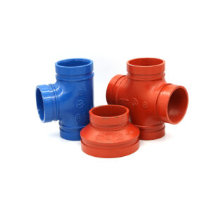
If you’re building a standard for your team, keep it tied to a consistent grooved system reference so field practice doesn’t drift from what was specified. For background on grooved piping products and technical resources, start at the manufacturer’s site: Vicast grooved piping systems.
Answer: Rigid vs flexible grooved coupling: which one to choose for fire sprinkler risers
Choose a rigid grooved coupling for sprinkler risers when the joint must behave as a restrained connection that keeps the vertical run aligned and transfers loads in a predictable way through hangers and bracing. Choose a flexible grooved coupling when the riser segment needs controlled angular deflection or small movement to accommodate thermal expansion, building drift, vibration, or planned transitions such as offsets and separation details. In real riser layouts, the best answer is often a mixed strategy: rigid where you want the riser to “stand straight,” flexible where you need the system to breathe without forcing strain into gaskets, bolts, and housings.
The selection becomes straightforward once you treat it as a measurable problem. First, determine how much movement the riser location will experience (temperature change, building motion, vibration). Second, determine how much restraint the riser must provide (alignment, load path, support behavior). Then verify the actual site conditions—alignment, strain, and installation quality—because forced fit-up can turn the “right coupling” into the wrong outcome.
What “rigid” and “flexible” mean in measurable terms
In a fire sprinkler riser, “rigid” and “flexible” are not marketing labels. They describe how the coupling handles relative pipe movement and how that movement shows up in real-world performance, especially at commissioning.
Rigid grooved coupling behavior on risers
A rigid grooved coupling is designed to restrict movement at the joint so the piping behaves more like a continuous run. In a vertical riser, that usually helps with alignment. When the riser is properly supported, rigid connections help maintain predictable geometry through floor lines, valve stations, and long straight shafts. That predictability matters when you’re trying to avoid side-loading components, rubbing at penetrations, or creating a riser that “walks” over time.
The practical takeaway is that rigid couplings generally belong where the riser should be stable—straight vertical sections, common valve train locations where alignment is critical, and segments where movement is not expected or is intentionally managed by other design features.
Flexible grooved coupling behavior on risers
A flexible grooved coupling is designed to allow limited movement—typically small angular deflection and controlled flexibility—without compromising the gasket seal when installed correctly. In riser work, flexibility is not about “sloppy installation.” It’s about not forcing the system to fight unavoidable conditions: thermal change, slight building drift, vibration from nearby equipment, or geometry transitions like offsets.
On a riser, the places that tend to demand flexibility are predictable. You’ll see it near transitions, around areas subject to motion, and in situations where a rigid joint would act like a hard point and shove the stress into a gasket.

The riser decision workflow that actually works in the field
If you want fewer call-backs and fewer debates during inspection, treat coupling selection as a short workflow rather than a habit.
Step 1 — Measure the movement demand (thermal, building drift, vibration)
This is the part many comparison articles skip. On risers, movement demand is not theoretical. Temperature swings between install, pressure test, and normal service can move steel. Buildings also move, even when everything looks “static.”
A practical measurement method starts with simple tools: a tape measure, a thermometer (or an infrared thermometer for surface checks), and your project documents. First, identify the riser segment you’re evaluating—especially around offsets, transitions, or long vertical runs between anchors. Second, estimate the temperature range the pipe will see from the day it’s installed to the day it’s in normal service. If you can measure water temperature during a test and compare it to expected operating conditions, even better. Third, note any building features that introduce motion: long spans, structural drift expectations, or separation details called out in the drawings.
Your decision criterion should be written plainly: if the location is expected to experience movement that could force the joint out of alignment or load the gasket unevenly, plan for a flexible coupling at that interface, or add design measures that control movement elsewhere. The common error here is assuming “vertical means no movement.” Another frequent mistake is using room temperature as a stand-in for pipe temperature during testing; it can be meaningfully different in a busy mechanical room.
Step 2 — Define the restraint requirement (what the riser must do)
A riser isn’t just a pipe; it’s part of a load path. It is supported, braced, and constrained at penetrations. Ask one direct question: does this segment need to behave like a restrained column to keep the system aligned? If yes, rigid couplings often make more sense because they reduce joint-level “give” that can show up as misalignment at fittings or penetrations.
If the segment needs to absorb motion, restraint becomes the enemy. That’s where flexible couplings can keep the system from fighting itself.
The common error at this step is mixing up restraint with “tightening harder.” Restraint is about system behavior, not torque alone.
Step 3 — Map coupling type to riser zones (base, mid-run, top, transitions)
Most risers can be divided into zones where the coupling choice becomes more obvious. The base of the riser and main tie-in areas tend to favor stability and alignment, which leans rigid. Long straight mid-run sections often use rigid to maintain predictable geometry when properly supported. Transitions—offsets, equipment connections, and areas influenced by motion—often benefit from flexible couplings because they reduce stress concentration at joints.
This zoning approach also improves purchasing and prefab consistency. You’re no longer deciding coupling type “one joint at a time.” You’re building a repeatable riser playbook.
How to verify on site whether a location needs rigid or flexible
Even a perfect design can be undermined by what shows up in the field. The best selection decisions are the ones you can verify with simple checks that don’t require guesswork.
Alignment tolerance check (the forced-fit problem)
A classic riser problem is forced fit-up. The pipe ends don’t naturally align, so the crew pulls them together and relies on the coupling to “make it work.” That can create hidden strain that shows up later as gasket weeping or repeat leaks after a pressure test.

You can verify this with basic tools: a straightedge, a level, and your eyes. The steps are straightforward. Before final tightening, check whether the pipe ends align naturally at the joint. If the pipe wants to spring away when supports are loosened slightly, the joint is under strain. Your decision criterion is simple: if alignment requires pulling, levering, or “muscling” the pipe into place, you either need to correct the layout/supports or use flexibility at that interface so the coupling isn’t carrying the misalignment as constant stress.
A common error is checking alignment only after the coupling is tightened. At that point, you’ve already forced the system into position and masked the strain.
Movement observation during fill and hydrostatic testing
Pressure testing can reveal behavior you don’t see when the system is dry. One practical method uses a marker and a ruler. Mark reference lines across the coupling housing and adjacent pipe so you can see if there is relative movement during pressurization or pump cycling. Then observe the joint during a controlled pressure ramp. If the joint shows visible angular change, or if a leak appears and disappears with pressure changes, it suggests the system is moving or vibrating in a way that a purely rigid approach may not tolerate at that location.
Your criterion should be conservative: repeated movement at a joint in a riser zone is a sign that flexibility, improved bracing, or better support strategy is needed. A common mistake is confusing momentary vibration with permanent deflection; stabilize pressure and observe in a steady state before calling it.
Code- and spec-driven selection without turning it into a guessing game
Fire sprinkler risers are rarely “choose whatever you like.” The project spec, authority requirements, and listed system expectations matter. Instead of arguing about terminology, treat compliance as a verification task.
A practical verification method uses three tools: the project submittal package, the job specification section for fire protection piping, and the coupling identification/marking on the part itself. The steps are to confirm that the coupling type used at a designated location matches the approved submittal for that riser detail and that it is intended for fire protection service. The decision criterion is that the installed component matches the approved detail for that location, including the coupling style required for movement or restraint. A common error is assuming “flexible is flexible,” then substituting products without confirming the intended service and the detail requirement.
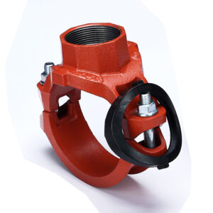
For crews and procurement teams, it helps to keep the coupling family accessible in one place so everyone is referencing the same system. The category hub at Grooved pipe fitting & coupling category is a logical internal anchor for your selection content and for related riser topics.
Installation and QA: the coupling type changes what you should inspect
Even the correct coupling choice can fail if installation quality is inconsistent. In riser work, the usual culprits are uneven tightening, mis-seated gaskets, and torque practices that substitute force for fit.
Bolt torque verification as a selection “reality check”
Whether rigid or flexible, the joint still relies on proper bolt tightening and a correct installed condition. A practical torque verification method needs only a torque wrench, the correct socket, and a marker. Mark the nut positions so you can track movement. Tighten in alternating steps so both sides load evenly. Then verify final torque with the wrench, rather than relying on an impact tool as the final word.
Your acceptance criteria should combine torque with symmetry. The coupling should reach its intended installed condition evenly, without one side drawing down far ahead of the other. If you hit the target torque but the joint still looks uneven, or if the joint requires excessive torque to settle, stop and recheck alignment and gasket seating. A common error is tightening one side to chase a small leak. That often worsens gasket distortion, especially in riser offsets where strain is already present.
How coupling choice affects troubleshooting
Rigid couplings can transmit strain. If a riser segment is misaligned or under movement, rigid joints may show problems as repeat leaks at the same location or stress at penetrations. Flexible couplings can absorb motion, but they can also hide poor support strategy if they’re used as a band-aid. The goal is not to “solve design problems with flexible couplings.” The goal is to use flexibility where it’s needed and build stable support everywhere else.
Common riser scenarios—and what each coupling choice does for you
Most selection decisions come down to a handful of scenarios that repeat across buildings.
When a riser leaks after a hydrostatic test at an offset, it often points to strain and uneven loading. A flexible coupling at the transition can reduce stress on the gasket, but only if the pipe fit-up and support are corrected so the coupling isn’t forced to compensate for a bad geometry.
When you see recurring drips at a floor penetration, the issue is often movement, rubbing, or poor clearance that turns normal building behavior into stress on the joint. A flexible coupling may help at the interface, but you should also evaluate guiding and penetration details so the riser isn’t being pushed sideways.
When you hear noise or feel vibration near pump rooms or mechanical equipment interfaces, flexibility can reduce the tendency for vibration to transmit into the riser. But again, it’s a system problem: flexible couplings work best when the support and alignment strategy makes sense.
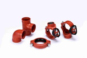
If you want to connect readers to concrete coupling options without turning the article into a sales pitch, link them to the manufacturer’s general product library at All products. It keeps the reader on your site and supports the broader cluster you’re building around risers, leakage, and installation QA.
The mixed strategy most risers end up using
In practice, “all rigid” and “all flexible” are both rare on well-executed projects. A mixed strategy is easier to defend because it ties each coupling choice to a measurable need. Use rigid couplings to maintain alignment and predictable riser behavior through long straight sections where movement is controlled and supports are correct. Use flexible couplings at interfaces where movement is expected or where small deflection prevents stress from building up at a hard point. Then verify the result with the same on-site checks: alignment before tightening, controlled tightening and torque verification, and observation during pressure testing.
That approach tends to reduce the two outcomes everyone hates: leaks that appear during commissioning and leaks that show up weeks later.
Hebei jianzhi Foundry Group Co., td. at a glance
Hebei jianzhi Foundry Group Co., td. is the manufacturing group behind the Vicast brand and states it has been producing pipe fittings since 1982. The company describes large-scale manufacturing capacity, an established engineering and quality management team, and management systems aligned with ISO 9001 for quality and ISO 14001 for environmental management. It also highlights international distribution across more than 100 countries and ongoing participation in standards work and patented technologies related to its product lines. For the official company profile and background, visit About Hebei jianzhi Foundry Group Co., td..
Conclusion
Rigid vs flexible grooved coupling decisions on fire sprinkler risers get easier when you stop treating them as a preference and start treating them as a measurable system behavior. Rigid couplings make sense where the riser must stay aligned and restrained. Flexible couplings make sense where motion, vibration, or transitions would otherwise force strain into joints and gaskets. The most dependable risers usually use a combination, backed by simple verification: measure movement demand, check fit-up alignment before tightening, confirm installation symmetry and torque, and observe behavior during pressure testing. That’s how you build risers that pass inspection today and stay dry later.
FAQs
Do I need a flexible grooved coupling on a sprinkler riser?
You may need a flexible grooved coupling on a sprinkler riser where controlled movement is expected, such as at offsets, transitions, or areas influenced by building motion or vibration. Verify by checking whether the pipe fit-up is naturally aligned and whether the joint shows movement during pressurization.
Where should I use rigid grooved couplings on fire sprinkler risers?
Rigid grooved couplings are commonly used on straight vertical riser sections where restraint and alignment are important and movement is controlled by proper supports and bracing. If the riser segment is intended to behave like a restrained column, rigid couplings are usually the better fit.
How can I tell if pipe strain is causing riser coupling leaks?
A practical sign is forced fit-up: if the pipe has to be pulled into alignment at the joint before tightening, the coupling may be carrying constant strain. Mark the joint and observe it during a stable pressure test; repeated leakage at the same location often points to strain rather than random gasket issues.
Can I mix rigid and flexible grooved couplings on the same sprinkler riser?
Yes. Many risers work best with a mixed strategy: rigid couplings for alignment and restraint on long straight runs, and flexible couplings where the system needs to accommodate movement at transitions or motion-influenced areas. The key is documenting why each location was selected and verifying installation quality.
Why does a flexible coupling still leak on a sprinkler riser?
Flexible couplings can leak if the gasket is pinched, tightening is uneven, the joint is under excessive strain, or torque practices are inconsistent. Flexibility does not replace proper fit-up, correct supports, and controlled tightening with a torque verification step.