How to measure groove diameter for grooved pipe fitting for fire sprinkler piping is a question that usually shows up when schedules get tight: the line is prepped for a hydrostatic test, a coupling won’t seat the way it should, or QA/QC needs something more solid than “it looked fine.” Plenty of search results hand you a groove dimension table, often buried in a PDF. What they don’t give you is a field-ready method with repeatable steps, clear pass/fail logic, and the common mistakes that cause good grooves to read bad (or bad grooves to slip through). This guide is written for installers, foremen, prefab shops, and inspectors who want a clean, defensible measurement they can repeat across a jobsite.

Answer: How to measure groove diameter for grooved pipe fitting for fire sprinkler piping
To measure groove diameter for grooved pipe fitting for fire sprinkler piping, you need to do two things: verify you’re measuring the correct dimension for the groove system you’re using, and measure it in a way that accounts for real-world variation around the pipe. In practice, most crews use a two-path approach. First, they run a Go/No-Go acceptance check with a groove gauge or diameter tape method to confirm the groove diameter falls within the allowable range. Second, when documentation or troubleshooting calls for it, they confirm the numeric value with calipers and repeat the measurement at multiple clock positions to catch out-of-roundness or localized defects.
The minimum standard that holds up in the field is straightforward: the groove diameter (often referred to as the “C dimension”) must be within the tolerance for the applicable grooved system and pipe size, and it must be consistent around the circumference. If it isn’t, you should treat the groove as nonconforming, because uneven groove geometry can lead to poor coupling engagement, gasket distortion, and avoidable leaks during testing or service.
Identify the groove system and the governing spec before you measure
Before you touch a tool, make sure your team is measuring against the right reference. “Grooved pipe” is not a single universal geometry. Different systems and pipe types come with their own tolerance tables and inspection language. In fire sprinkler work, that matters because a groove that is slightly off might still look acceptable to the naked eye, yet it can change how the housing keys sit in the groove and how the gasket compresses under pressure.
This is also where people waste time. A crew measures a diameter, compares it to the wrong table, calls it out of spec, and starts reworking pipe ends that were actually fine. On the other side, someone assumes “close enough,” doesn’t check the right tolerance, and ends up chasing leaks at commissioning.
Roll grooving vs cut grooving: why the method affects the result
Roll grooving and cut grooving don’t behave the same in the field. Roll grooving can be more sensitive to pipe ovality and coating buildup, while cut grooving can be more sensitive to burrs and tool wear. Either method can produce conforming grooves, but the failure signatures differ. If you’re troubleshooting an inconsistent groove diameter around the pipe, it’s useful to know which process made the groove, because it points you toward the likely cause—machine setup, feed pressure, tool condition, or pipe roundness.
Tools you need and what each tool is really telling you
For a measurement to be useful, it has to be repeatable. That means the tool needs to match the question you’re asking.
Go/No-Go tools: groove gauge and diameter tape checks
A Go/No-Go approach is the fastest way to confirm groove diameter acceptability during production or field acceptance. The “win” here is speed and consistency. Instead of chasing decimals, the gauge tells you whether the groove diameter falls within a marked range for that pipe size and grooving system. That’s exactly what most crews need when they’re processing dozens of pipe ends.
The key is to use the correct gauge for the groove system and pipe size you’re working with. If you use the wrong gauge, the reading may look authoritative but be meaningless. That’s not a small mistake; it can ripple through a whole prefab batch.
Numeric tools: calipers and diameter measurements for documentation
When you need to document results for QA records, disputes, or repeated leakage troubleshooting, numeric measurement becomes important. Calipers can help you confirm groove diameter values and, more importantly, reveal variability around the pipe. A single “good” measurement doesn’t prove a groove is good if another point around the circumference fails. Measuring at multiple points is what turns a number into evidence.
Calipers do have limits. On heavily coated pipe, a caliper can read the coating rather than the metal geometry you care about, and that can lead to false failures. That’s why you should treat coated pipe as its own case, not a footnote.
Step-by-step: Go/No-Go method to verify groove diameter
Most search results assume you already know how to do this. In real fire sprinkler installations, the details matter.
Prep and cleaning: keep the reading honest
Start by cleaning the pipe end around the groove. Dirt, scale, paint buildup, and small metal slivers can all change what your gauge “sees.” If the pipe end is greasy or packed with debris, the gauge may not sit flat and you’ll chase a phantom problem. Wipe the area and remove obvious burrs. You’re not polishing the pipe; you’re clearing the measurement surface.
Next, confirm you’re working on the correct pipe end. It sounds obvious, but on busy prefab lines, mixed batches happen. A groove gauge does not tell you you grabbed the wrong pipe schedule or wrong grooving setup. It will simply tell you the geometry doesn’t match.
Measurement procedure: tools, steps, and repetition
Place the gauge or diameter tape squarely at the groove location as designed, keeping it level and seated. Apply steady, consistent tension. Don’t yank it tight on one check and pull it lightly on the next. Consistency is the difference between a reliable Go/No-Go process and a guessing game.

Then repeat the check at multiple clock positions around the pipe—think of a quick three-point pattern. If the groove passes on one side and fails on the other, that is not “a weird reading.” That’s a diagnostic clue that the groove may be inconsistent, the pipe may be slightly out of round, or the grooving setup is producing uneven geometry.
Pass/fail criteria: a rule that crews can follow
Your pass/fail rule should be written down and used the same way every time. If the gauge indicates the groove diameter falls within the acceptable range for the correct pipe size and groove system, it passes. If it falls outside that range at any position around the pipe, it fails and should be addressed. In fire sprinkler piping, “mostly passes” is not a comfortable middle ground, because a localized out-of-tolerance section can still compromise coupling engagement and gasket compression.
Common error sources: why readings jump around
If two people measure the same groove and get different results, it’s usually not bad luck. The usual culprits are inconsistent tension, reading at an angle, measuring over coating buildup, using a gauge for the wrong system, or skipping multi-point checks. Another common problem is trying to measure too close to the pipe end where edge conditions and flare can distort how a tool seats. When in doubt, slow down and verify you’re positioned correctly.
Step-by-step: Numeric confirmation with calipers
When the job requires documentation or you’re chasing a stubborn seating issue, this is the method that gives you the clearest story.
What you’re measuring: groove diameter and why it’s called “C dimension”
In many grooving references, groove diameter is labeled as the C dimension. In plain language, it’s the diameter at the groove location that determines how the housing keys engage and how the gasket is compressed by the coupling geometry. If your team measures the pipe OD instead, or measures across the wrong feature, the result will not predict real performance. That’s why it’s worth defining the dimension clearly in your internal SOP and training.
Procedure: tools, steps, and the “three-point truth”
Use calipers suited for the diameter range. Measure the groove diameter at three or more positions around the pipe. Record each reading rather than averaging on the fly. The spread between the highest and lowest reading is often more informative than the average, because it points to out-of-roundness, uneven grooving, or localized damage.
If you want this measurement to hold up under scrutiny, note the pipe size, the measurement positions you used, the tool type, and whether the pipe has coating at the groove. Those details explain why a number is what it is, and they help another person reproduce the result.
Acceptance criteria: how to decide on borderline readings
Compare your readings to the tolerance for your groove system and pipe size. If one position fails while others pass, treat it as a real nonconformance unless you can trace the failure to a measurement error such as obvious coating buildup or tool misalignment. A groove does not need to be bad “everywhere” to create problems; one out-of-tolerance segment can be enough to produce uneven gasket compression and intermittent leakage.
Coated pipe adjustment: the detail that prevents false rejects
Coated sprinkler pipe is common, especially on jobs where corrosion resistance is a concern. Coating can build up around the groove and change tool seating and measured values. If you measure over coating, you may reject a groove that is geometrically fine. The practical move is to measure in a way that reflects the metal geometry or account for coating thickness where appropriate. If coating is heavy and uneven, the best decision may be to clean the measurement area at the groove location so your readings represent the feature that actually matters for coupling engagement.
Troubleshooting: what to do when groove diameter is out of tolerance
When a groove fails, the next step should be deliberate. Reworking pipe ends without understanding the failure mode can create scrap and schedule pain.
If the groove diameter indicates the groove is too shallow or too deep, the corrective action is usually a controlled re-groove or re-cut using a verified setup. If the failure appears only at one clock position, look first at pipe roundness and machine alignment. Pipe that is slightly oval can yield grooves that pass on one side and fail on the other. In that case, you may need to correct the pipe end condition or adjust the grooving process to compensate.
If measurements are inconsistent and you also see coupling fit issues, don’t ignore pipe end defects. Burrs, dents, and heavy edge conditions can interfere with gasket seating even when the groove diameter is technically within tolerance. A groove diameter number is powerful, but it’s not the only variable in a leak-free joint.
Preventive QC workflow for sprinkler grooving
The fastest teams don’t measure because something went wrong. They measure because they don’t want surprises.
A practical workflow starts with a first-article check when the grooving equipment is set up. Once the first piece is verified, continue with periodic checks during production and after any change that could affect geometry—tool changes, machine adjustments, or a shift to a different pipe batch. Over time, this prevents the “one bad batch” scenario that shows up during commissioning when it’s hardest to fix.
Documentation should be light but consistent. Record pipe size, groove system, method used, groove diameter readings at multiple positions, and a pass/fail call. When a project crosses multiple teams—prefab, install, inspection—those records reduce arguments and accelerate decisions.
Tie the measurement back to the grooved system you’re installing
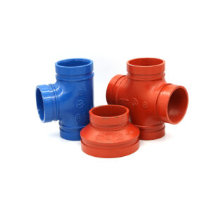
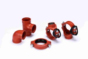
If you want fewer headaches, keep measurement guidance connected to the actual product system used on the job. That means your crew should be able to look up coupling and fitting families quickly, confirm what groove system they’re working with, and keep measurement tools aligned to that system.
For product context and system continuity, you can route readers to the main site at Vicast grooved piping systems and then to the broader catalog at All products. For teams working specifically with grooved couplings and related fittings in sprinkler piping, the most relevant hub is Grooved pipe fitting & coupling category, which is a natural place to connect measurement practice with the components being installed.
Hebei jianzhi Foundry Group Co., td. at a glance
Hebei jianzhi Foundry Group Co., td. is the manufacturing group behind Vicast and states a long production history in pipe fittings dating back to 1982. The company highlights large-scale manufacturing capacity, a sizable engineering team supporting product development and quality management, and systems aligned with ISO 9001 and ISO 14001. It also describes broad international distribution and ongoing work tied to standards and patented technologies. For a concise overview of the company background and capabilities in one place, visit About Hebei jianzhi Foundry Group Co., td..
Conclusion
Measuring groove diameter in fire sprinkler piping doesn’t have to be a guessing game or a PDF scavenger hunt. The field-proven approach is to verify the correct groove system first, run a Go/No-Go acceptance check for fast conformance, and then use calipers for numeric confirmation when documentation or troubleshooting demands it. The real difference-maker is multi-point measurement: checking more than one location around the pipe catches the out-of-roundness and localized defects that cause uneven coupling engagement and gasket compression. When you treat groove diameter as a measurable input to joint performance, you reduce rework, speed up commissioning, and make your QA decisions easier to defend.
FAQs
Where do I measure groove diameter on a grooved pipe for fire sprinkler piping?
Measure groove diameter at the groove location specified for your grooving system, focusing on the feature often labeled as the C dimension. For reliable results, measure at multiple positions around the pipe, not just one spot, because a localized defect can still affect coupling engagement.
Why does my Go/No-Go gauge pass on one side and fail on the other?
That pattern usually indicates out-of-round pipe, uneven grooving, or inconsistent tool seating due to coating or debris. Recheck the measurement with consistent tension and confirm with calipers at three or more clock positions to see whether the groove diameter varies around the circumference.
Can I measure groove diameter on coated sprinkler pipe?
Yes, but you need to account for coating thickness and uneven buildup. If the coating is heavy at the groove, it can distort how a gauge seats or how calipers read the diameter. Cleaning the measurement area at the groove location is often the most practical way to get a trustworthy result.
What should I do if the groove diameter is out of tolerance?
Treat it as nonconforming and stop before you install couplings on that pipe end. Depending on the failure mode, the corrective action is usually re-grooving with a verified setup, correcting pipe-end defects, or addressing pipe ovality that is producing inconsistent geometry.
Why does groove diameter matter if the coupling “seems to fit”?
A coupling can feel like it fits while still being at risk. Groove diameter affects how the housing keys engage the groove and how evenly the gasket compresses under pressure. When groove diameter is out of tolerance or inconsistent, the joint is more likely to leak during hydrostatic testing or after the system cycles.