Abstract
From hands-on work in the field, hydrostatic testing works as the key check to confirm the build strength, no-leak seal, and pressure hold of grooved pipe fitting setups before they start running. Water supply lines, from town water grids to plant fire safety rings, depend on this test pressure as the main pass mark. This guide lays out the basic setup for figuring, carrying out, and noting hydrostatic pressure tests on raccordi per tubi a scanalatura. It stresses the 1.5× design pressure boost set by ASME B31.3 and the 4× burst safety edge needed by UL 213 for fire protection jobs.
Pulling from core ideas in end load force math—P × A—this resource gives the number base to grasp why a 4-inch accoppiamento a scanalatura at 300 psi working pressure has to handle more than 11,000 pounds of pull force before the rubber gasket seals up. Looking at the needs from ASTM F1476, AWWA C606 for water jobs, and UL 213 for fire uses, it sets up a full test plan. Procurement leads, site bosses, and quality teams can put it to use at once. The math L = h / R for service life guess, pulled from rust engineering basics, shows how good hydrostatic testing ties right to 50-year system steadiness. Starting with gasket push-out weak spots to the proper bolt tighten order for stiff and bendy couplings, this paper acts as the main site tool to make sure each grooved pipe fitting setup hits—and beats—the pressure needs of current water supply setups.

Key Takeaways
The Hydrostatic Test Multiplier (1.5× Design Pressure): Under ASME B31.3, the base hydrostatic test pressure for pipe systems uses P_test = 1.5 × P_design × (S_t / S_d). For room-heat water supply lines, it cuts down to 1.5 × design pressure. So, a line set for 300 PSI working pressure needs to prove hold at 450 PSI hydrostatic test pressure. No clear leaks or lasting bends should appear.
The End Load Force Formula (P × A): The pull force on a grooved coupling at test pressure comes from pressure (P) times the pipe’s inner cut area (A). For a 4-inch Schedule 40 pipe (4.5-inch OD, cut area 15.90 in²), at 450 PSI test pressure, the end load hits 7,155 pounds. The grooved coupling and bolts must bear this force. No joint split or gasket push should happen.
Safety Factor Multipliers by Application: Mechanical jobs (ASTM F1476) need 3× rated pressure for hydrostatic hold. Fire protection jobs (UL 213, FM 1920) call for 4× rated pressure in burst checks. A coupling set for 300 PSI in water supply must bear 900 PSI (mechanical) or 1,200 PSI (fire protection) before build fail.
The Gasket Extrusion Failure Mode: The top hydrostatic test fail in grooved pipe fittings is gasket extrusion. Here, the rubber seal gets pushed from the groove space by high pressure gap. It happens with low bolt torque (under maker’s 60–75 ft-lbs for 4-inch couplings). Or when groove shape strays from AWWA C606 limits.
Bolt Torque as the Control Variable: For grooved couplings, even bolt torque on each bolt is the main install factor. Uneven torque makes spotty gasket press. This leads to leak spots at weak press areas. Use a set torque wrench—not impact tools—for all tested joints.
Temperature Compensation Requirement: Adjust test pressure for heat when test heat differs from design heat. The S_t / S_d ratio covers lower allowed stress at higher heats. For hot water lines at 180°F, figure test pressure with stress values at that heat.
Documentation and Traceability: Each hydrostatic test needs a full test set. Include P&ID reference, test pressure math sheet, ongoing pressure and heat logs, check notes, and material test certificates (MTCs) for all fittings in the test part. This record acts as the lasting quality proof for system start and insurance okay.
Gasket Compatibility Verification: The rubber gasket type—often EPDM for water supply, nitrile for oil jobs, or silicone for high-heat uses—must match the test fluid and heat range. EPDM gaskets wear down when hit with oil-based lubes or test liquids.

Tabella dei contenuti
Introduction: The Role of Hydrostatic Testing in Grooved Pipe Systems
Regulatory Framework and Applicable Standards
Hydrostatic Test Pressure Calculation: The Engineering Foundation
End Load Force Analysis: Understanding the Physical Demands on Grooved Couplings
Test Preparation: System Isolation and Safety Protocols
Test Execution Procedure: Step-by-Step Field Protocol
Gasket Performance Under Hydrostatic Pressure: Failure Mode Analysis
Bolt Torque Requirements and Joint Integrity
Common Test Failures and Corrective Actions
Documentation, Reporting, and Compliance
The Vicast® Advantage: Hebei Jianzhi Foundry Group Co., Ltd. Quality Assurance
Conclusione
References
Domande frequenti
Notes on References
1. Introduction: The Role of Hydrostatic Testing in Grooved Pipe Systems
Hydrostatic testing acts as the main check method to confirm the build strength, no-leak seal, and pressure hold of grooved pipe fitting setups before start-up. In water supply fields—from town water grids, plant process water paths, HVAC cold and hot water lines, to fire sprinkler systems—this test works as the last hurdle. Every joint, coupling, and fitting must clear it before the system runs.
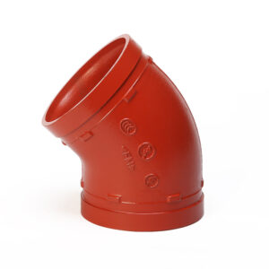
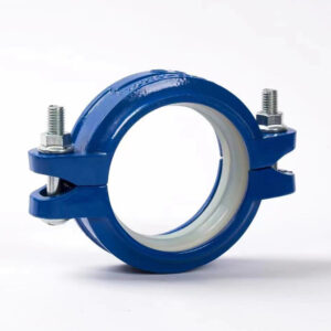
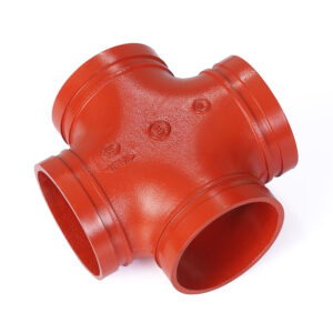
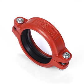
Grooved pipe fittings have changed pipe join methods. They stand apart from welded, flanged, or threaded links. Grooved fittings use a mechanical coupler. It presses a rubber gasket into a pre-cut groove on the pipe end. This forms a pressure-boosted seal. The seal tightens as inside pressure rises. Such a setup brings clear gains in install speed, upkeep ease, and system bend. Yet, it adds specific fail types. Gasket push-out and groove slip stand out. They require strict hydrostatic checks.
This guide seeks to offer engineers, buyers, site leads, and quality staff a full plan for hydrostatic testing of grooved pipe fittings in water supply jobs. It draws from end load force ideas—P × A. Thus, it builds the number base to see why a 4-inch grooved coupling at 300 PSI working pressure must bear over 11,000 pounds of pull force before the rubber gasket seals.
Hydrostatic testing beats a mere rule tick. It ranks as the top non-harm check to prove a pipe system can safely hold its design pressure for its full run life. Water—a non-squeeze fluid—pressures the pipe inside. Any flaw then shows as clear leaks, lasting bends, or big fails. Air testing stores huge energy in squeezed gas. It can cause blast fails. Water testing caps stored energy at test pressure. Hence, it proves safer and more common for most jobs.
For grooved pipe fittings in particular, the hydrostatic test checks three main work traits:
Seal Integrity: The rubber gasket must keep press against groove walls at test pressure. No push-out, slow shift, or leaks.
Structural Strength: The coupling body and bolts must bear the figured end load force. No bend, crack, or joint split.
Groove Conformance: The pipe-end groove must match AWWA C606 size limits. This stops slip under pull tension.
This guide points to Hebei Jianzhi Foundry Group Co., Ltd.—a 40-year trade leader under the Vicast® brand—as the quality mark for rule-follow grooved fitting makes. With ISO 9001 approval, UL/FM/CE product stamps, and current auto lines in its 1.4 million m² site, Jianzhi shows the quality mark that hydrostatic testing aims to check.
2. Regulatory Framework and Applicable Standards
A broad set of world rules guides hydrostatic testing of grooved pipe fittings for water supply. Each rule handles certain test plan parts. These range from pressure boosts and hold times to pass marks and record needs.
2.1 ASME B31.3: Process Piping
ASME B31.3 acts as the lead code for process pipe systems. This includes plant water supply nets. Section 345 lists rules for hydrostatic testing. Key points cover:
Test Pressure Formula: P_test = 1.5 × P_design × (S_t / S_d). S_t is allowable stress at test heat. S_d is allowable stress at design heat.
Hold Time: Least 10 minutes at test pressure. Field tests of full systems often run 1–2 hours.
Acceptance Criterion: No clear leaks. No pressure fall from heat or bend effects.
Test Medium: Clean, treated, rust-stop water.
For room-heat water supply systems, the S_t / S_d ratio equals 1.0. This makes test pressure math simple: 1.5 × design pressure.
2.2 AWWA C606: Grooved and Shouldered Joints
AWWA C606 gives size and work rules for grooved joints in water, waste, and reuse water service. First out in 1978 and last changed in 2022, it sets least needs for groove sizes, limits, and design proof tests.
Main AWWA C606 rules linked to hydrostatic testing include:
Groove Profiles: Set groove depth, width, and curve sizes for pipes ¾” to 64″ across.
Hydrostatic Strength Test: AWWA C606 needs hydrostatic testing to 37.5 bar (about 544 PSI) for water fittings. No leaks allowed.
Burst Test Requirement: ASTM F1476 burst testing to ≥75 bar (about 1,088 PSI) for mechanical jobs.
Most North American and world water utility specs cite AWWA C606. Any grooved pipe fitting in a town water system must follow its groove sizes for coupler match.
2.3 UL 213: Rubber Gasketed Fittings for Fire-Protection Service
For fire protection water lines, UL 213 sets the toughest hydrostatic testing rules. It covers rubber gasket fittings for joining pipe parts in fire systems. This includes couplings, elbows, tees, and side outlets.
UL 213 lists these hydrostatic tests:
Hydrostatic Strength Test: The fitting must hold 4× rated pressure. No leaks or lasting bends.
Cyclic Pressure Test: 5,000 cycles from normal to rated pressure at 10–30 cycles per minute. No leaks.
Gasket Compression Retention: Gaskets pressed at high heat (70°C for 22 hours) must keep seal power.
Corrosion Resistance: 200-hour salt spray test per ASTM B117.
For a 300 PSI rated fitting in water supply, UL 213 needs burst testing to 1,200 PSI before stamp. This 4× safety edge gives the needed room for life-safety systems. Fails can’t occur there.
2.4 ASTM F1476: Standard Specification for Performance of Gasketed Mechanical Couplings
ASTM F1476 is the trade standard for testing gasketed mechanical couplers. It sets least work for hydrostatic strength, bend load resist, and cycle pressure tests.
Key ASTM F1476 test details:
Hydrostatic Strength: Rated pressure × 3 (least).
Bending Moment Resistance: The coupler must fight set bend loads. No leaks or joint split.
Vacuum Test: -0.85 bar for 24 hours. No leaks allowed.
ASTM F1476 guides both UL and FM for mechanical work tests.
2.5 ISO 6182: Fire Protection — Automatic Sprinkler Systems
ISO 6182 gives the world frame for grooved fitting tests in fire protection. It lines with AWWA C606 for groove sizes. It cites UL 213 for hydrostatic test plans.
Vicast® grooved pipe fittings meet ISO 6182 size rules. This ensures match with world coupler systems.
2.6 Summary of Standard Requirements
| Standard | Applicazione | Test Pressure (Hydrostatic Strength) | Burst Requirement | Hold Time |
| ASME B31.3 | Process piping | 1.5 × design pressure | N/A (proof test) | ≥10 min |
| AWWA C606 | Water service | 37.5 bar (544 PSI) | ≥75 bar (1,088 PSI) | Per spec |
| UL 213 | Protezione antincendio | 4 × rated pressure | 4 × rated pressure (minimum) | 60 sec minimum |
| ASTM F1476 | Mechanical couplings | 3 × rated pressure | 3 × rated pressure (minimum) | Per spec |
| EN 10242 | European water service | 25 bar (363 PSI) | ≥50 bar (725 PSI) | No leakage criteria |
For water supply jobs across many areas, the toughest rule often leads. Fire protection needs UL 213 match (4×). Town water works need AWWA C606 (37.5 bar hydrostatic). Plant process water follows ASME B31.3 (1.5× design pressure). Buyers should check fitting codes before setting test plans.
3. Hydrostatic Test Pressure Calculation: The Engineering Foundation
Figuring hydrostatic test pressure for a grooved pipe fitting system follows basic engineering ideas. These balance safety proof with build guard.
3.1 The ASME B31.3 Test Pressure Formula
The ASME B31.3 math for least hydrostatic test pressure is:
P_test = 1.5 × P_design × (S_t / S_d)
Where:
P_test = Least hydrostatic test pressure (gauge pressure)
P_design = Inside design gauge pressure
S_t = Allowed stress at test heat
S_d = Allowed stress at design heat
For room-heat water supply systems where test heat roughly equals design heat (often 20–30°C), the S_t / S_d ratio equals 1.0. The math then simplifies to:
P_test = 1.5 × P_design
3.2 Practical Test Pressure Values
For usual water supply pressure types:
| Design Pressure | Test Pressure (1.5×) | Applicazione |
| 150 PSI (10.3 bar) | 225 PSI (15.5 bar) | Low-pressure distribution |
| 175 PSI (12.1 bar) | 263 PSI (18.1 bar) | Standard sprinkler systems |
| 200 PSI (13.8 bar) | 300 PSI (20.7 bar) | Industrial water loops |
| 250 PSI (17.2 bar) | 375 PSI (25.9 bar) | High-rise fire protection |
| 300 PSI (20.7 bar) | 450 PSI (31.0 bar) | Process water, high-demand systems |
3.3 Temperature Compensation Factor
When test heat differs much from design heat, apply the S_t / S_d ratio. For carbon steel and ductile iron grooved fittings, allowed stress drops as heat rises.
Take this example. A hot water supply system has design heat of 180°F (82°C) and allowed stress S_d = 17,500 PSI. Test at room heat 70°F (21°C) where S_t = 20,000 PSI.
S_t / S_d = 20,000 / 17,500 = 1.14
P_test = 1.5 × P_design × 1.14 = 1.71 × P_design
A system set for 200 PSI at 180°F would need a test pressure of 342 PSI at room heat.
3.4 Maximum Test Pressure Limitations
ASME B31.3 caps test pressure at the level that would cause normal pressure stress or length stress over 90% of yield strength for any part at test heat. This rule shields the pipe system from over-strain during test.
For grooved pipe fittings, the coupler body or bolts often set the cap. Vicast® grooved fittings have enough room. Thus, the 1.5× test pressure multiplier stays under the 90% yield cap for all standard pressure types.
3.5 Test Pressure for Fire Protection Systems (UL 213)
UL 213 needs a 4× rated pressure hydrostatic strength test. For a fitting set at 300 PSI:
P_burst_min = 4 × 300 PSI = 1,200 PSI
This is not a field test need—it is a factory stamp test. Field hydrostatic testing for fire systems follows NFPA 13. It needs 200 PSI or 50 PSI over system working pressure, whichever is higher.
4. End Load Force Analysis: Understanding the Physical Demands on Grooved Couplings
End load force ranks as the top engineering factor in grooved coupling design and testing. When a pipe system gets pressure, inside pressure pushes a pull force on each joint. The grooved coupling must fight this force. It does so through the coupler body’s lock with the pipe groove.
4.1 The Fundamental Formula: P × A
The pull force uses this math:
F_end = P × A
Where:
F_end = End load force (pounds or Newtons)
P = Inside pressure (PSI or kPa)
A = Inside cut area of the pipe (in² or m²)
4.2 Calculating Pipe Internal Area
For a standard 4-inch Schedule 40 steel pipe:
Nominal diameter: 4 inches
Outside diameter (OD): 4.5 inches
Wall thickness (t): 0.237 inches
Inside diameter (ID): OD – (2 × t) = 4.5 – 0.474 = 4.026 inches
Internal area: (ID² × π) / 4 = (4.026² × 3.1416) / 4 = 12.73 in²
Or, using the OD method common in coupling engineering:
Area based on OD: (4.5² × π) / 4 = 15.90 in²
Trade practice for coupling design uses the OD-based area. The coupling must hold the full pipe cut section, not just the inner bore.
4.3 End Load Force at Test Pressure
For a 4-inch system tested at 450 PSI (1.5 × 300 PSI design):
F_end = 450 PSI × 15.90 in² = 7,155 pounds
For UL 213 stamp testing at 1,200 PSI:
F_end = 1,200 PSI × 15.90 in² = 19,080 pounds
This is the pull force the grooved coupling must fight. The coupling body passes this force from the pipe groove through its build to the bolts.
4.4 Bolt Load Requirements
Bolts in a grooved coupling must give enough clamp force to stop the coupling bodies from splitting under end load. For a 4-inch coupling with two bolts, each bolt bears about half the total end load:
F_bolt_per_bolt = F_end / (number of bolts × bolt load factor)
Usual bolt torque values for grooved couplings:
| Pipe Size | Bolt Size | Recommended Torque (ft-lbs) | Approximate Clamp Force (lbs per bolt) |
| 2″ | 5/8″ | 45–60 | 4,500–6,000 |
| 3″ | 5/8″ | 60–75 | 6,000–7,500 |
| 4″ | 3/4″ | 60–75 | 7,000–8,700 |
| 6″ | 7/8″ | 75–90 | 9,000–10,800 |
| 8″ | 1″ | 90–110 | 12,000–14,700 |
Values approximate and change by maker. Always check the coupling maker’s torque guides. Vicast® gives torque tables for all grooved coupling items.
4.5 Safety Factor Application
The hydrostatic test pressure builds in safety edges over working pressure. Thus, the end load force at test pressure shows a tougher state than regular run. This is on purpose. The test proves the system keeps strength under overload states that top normal job needs.
For fire protection jobs with UL 213 stamp, the 4× burst test adds a safety edge of 4 to working pressure. This leads to end load forces four times above normal run states. Such a wide edge makes sure the coupling won’t fail in any real fire protection run case.
5. Test Preparation: System Isolation and Safety Protocols
Right test prep is vital for safety and true results. Finish these steps before pressure starts.
5.1 System Isolation
Remove or cut off all parts whose max allowed hydrostatic test pressure is below the figured test pressure. This often includes:
Pressure relief valves (set below test pressure)
Expansion joints
Sensitive instrumentation (pressure transmitters, flow meters)
Control valves with pressure ratings below test pressure
Isolation happens by:
Installing blind flanges (ASME B16.5 or B16.47) at all open ends
Using spectacle blinds or spade blinds in closed position
Removing instruments or isolating them with block valves and blind flanges
5.2 Test Boundary Identification
Mark test section limits clearly on P&ID drawings and in the field. Fence the hydrostatic test zone with signs warning staff of the active test.
5.3 Valve Positioning
In-line valves: Open position
Drain valves: Closed position
Sampling ports: Closed position
Vent valves: Open during filling, closed during pressurization
5.4 Test Medium Specifications
The test medium is typically clean, treated water:
pH neutral (6.5–7.5)
Non-toxic
Portable or demineralized quality
Free from suspended solids, oils, and contaminants
Temperature maintained between 40°F and 100°F (4–38°C) to prevent freezing and avoid brittle fracture concerns
5.5 Equipment Requirements
Hydraulic pressure pump (capable of exceeding test pressure by 25%)
Calibrated pressure gauge (accuracy ±1% of full scale)
Temperature measurement device
Data recorder (continuous pressure and temperature logging)
Torque wrench (calibrated) for bolt checks
Safety barriers and personal protective equipment for all personnel
5.6 Pre-Test Visual Inspection
All grooved joints in the test section should be visually inspected before pressurization:
Verify correct coupling size for pipe diameter
Confirm gasket is properly seated in the groove
Check that coupling housings are aligned and bolts are engaged
Ensure bolts are snug-tight (hand-tight plus 1–2 wrench turns)
6. Test Execution Procedure: Step-by-Step Field Protocol
The hydrostatic test run follows a managed, step rise plan. It aims to boost safety while getting true test outcomes.
6.1 Filling and Venting
The system is filled from the lowest point to ensure complete filling and to facilitate air removal.
Procedure:
Open all vent valves at high points in the system.
Begin filling slowly from the lowest fill point.
Maintain fill rate below 10 gallons per minute to avoid hydraulic shock and allow trapped air to escape.
Continue filling until water flows steadily from the highest vent valve, indicating complete air evacuation.
Close vent valves in sequence from lowest to highest.
Allow temperature to equalize between test fluid and piping material to within ±5°C (±9°F).
Critical note: Trapped air compresses unpredictably and reduces test reliability. Incomplete venting is a leading cause of false test failures and dangerous pressure spikes.
6.2 Initial Pressurization
Procedure:
Gradually increase pressure to 50% of the calculated test pressure.
Hold at 50% for 5 minutes to allow system stabilization.
Conduct initial visual inspection of all joints, welds, flanges, and connections.
If no leaks or anomalies are observed, proceed to full test pressure.
Increase pressure in controlled increments: 25%, 50%, 75%, then 100% of test pressure.
Hold at each increment for 2–3 minutes for inspection.
6.3 Hold Period at Test Pressure
Procedure:
Maintain the calculated test pressure for the required hold time.
For ASME B31.3, minimum hold time is 10 minutes at test pressure.
For field testing of complete water supply systems, 1–2 hour hold periods are common.
Record pressure and temperature continuously throughout the hold period.
Walk down all joints, couplings, flanges, and connections during the hold period.
Inspect for:
Visible leakage (water seepage, droplets, or streaming)
Gasket extrusion (elastomer protruding from coupling)
Sweating or weeping through porous castings
Pressure drop beyond thermal or elastic effects
Permanent deformation of coupling housings or bolts
6.4 Acceptance Criteria
The system passes the hydrostatic test if:
No visible leakage is observed at any joint, coupling, fitting, or connection.
No pressure drop beyond that attributable to temperature stabilization (typically less than 1–2% over the hold period).
No permanent deformation of any component is observed after depressurization.
No gasket extrusion or displacement is detected.
The system fails the hydrostatic test if:
Any visible leakage occurs at test pressure (including weeping, sweating, or droplets).
Pressure drops exceed 5% of test pressure over the hold period without corresponding temperature decrease.
Coupling housings show visible separation or bolt stretching.
Gaskets are extruded from the coupling housing.
6.5 Depressurization
Procedure:
Reduce pressure gradually—never open a valve fully or rapidly.
Controlled depressurization rate: 25–50 PSI per minute.
Open drain valves at low points.
Open vent valves at high points to admit air and prevent vacuum collapse.
After complete depressurization, inspect all joints again for signs of leakage or damage that may have been masked by system pressure.
Drain, dry, and preserve the system as required by the project specification.
6.6 Post-Test Bolt Re-torquing
For grooved couplings, bolt re-torquing after hydrostatic testing is recommended but must be performed at zero pressure. The procedure is:
Confirm system is completely depressurized and drained.
Using a calibrated torque wrench, check each bolt in sequence.
Apply torque to the manufacturer’s specified value (e.g., 60–75 ft-lbs for 4-inch couplings).
Follow the cross-tightening sequence (star pattern) to ensure even gasket compression.
Record final torque values in the test documentation.
6.7 Special Considerations for Flexible Couplings
Flexible grooved couplings are designed to allow axial and angular pipe movement. During hydrostatic testing of flexible couplings:
The coupling must be centered on the pipe ends—gap between pipe ends must conform to manufacturer specifications (typically 1/8″ to 3/8″ for sizes up to 8 inches).
Angular deflection within the coupling’s rated capacity is permissible.
The pipe ends must be grooved to AWWA C606 specifications—rolled grooves are preferred for flexible couplings.
7. Gasket Performance Under Hydrostatic Pressure: Failure Mode Analysis
The rubber gasket forms the seal core of every grooved pipe fitting. Knowing gasket fail types under hydrostatic pressure helps spot test issues and avoid future site problems.
7.1 The Pressure-Energized Seal Principle
Grooved coupling gaskets boost with pressure—as inside pressure grows, the gasket presses firmer against the coupling body and pipe groove walls. This is a basic gain of grooved tech: higher pressure makes a firmer seal, up to the gasket’s material edge.
The gasket cut has seal lips that touch the pipe groove. When pressured, these lips spread against groove walls. They create a no-leak block.
7.2 Primary Gasket Failure Modes
Mode 1: Gasket Extrusion
Gasket extrusion happens when the rubber gets pushed from the groove space by high pressure gap. A leaking gasket may show warped or pushed material beyond its first size. This points to weak load hold.
Causes:
Bolt torque below manufacturer specification
Groove depth or width outside AWWA C606 tolerances
Gasket material incompatible with test medium (e.g., EPDM exposed to hydrocarbons)
Excessive test pressure beyond coupling rating
Pipe ends not fully seated (gap too wide)
Corrective actions:
Increase bolt torque to specification using calibrated torque wrench
Verify groove dimensions with GO/NO-GO gauge
Replace with correct gasket material
Reduce test pressure to within coupling rating
Re-seat pipe ends to correct gap dimension
Mode 2: Creep and Compression Set
All rubber materials show creep under long press—a slow loss of bounce over time. When the gasket sets permanent, seal force drops. Leaks may follow.
Causes:
Gasket aged beyond service life
Elevated test temperature accelerating material degradation
Excessive initial compression (over-torqued bolts)
Chemical incompatibility causing material softening
Corrective actions:
Replace gaskets on a scheduled basis (manufacturer recommends 10–15 years for EPDM water service)
Maintain test temperature within gasket rating (EPDM: -40°C to 150°C)
Apply torque to specification, not beyond
Verify gasket compatibility with test fluid and system media
Mode 3: Chemical Degradation
If the gasket material is not compatible with the test medium or system fluid, chemical attack can degrade, crack, or soften the material.
Symptoms:
Uneven discoloration of gasket surface
Surface cracking or checking
Softening or tackiness of elastomer
Loss of structural integrity
Corrective actions:
Select correct gasket material for application:
EPDM: Water, wastewater, HVAC, fire protection
Nitrile (NBR): Oils, fuels, hydrocarbons
Silicone: High-temperature applications (200°C+)
Viton®: Chemical resistance, aggressive media
Verify chemical compatibility before testing
Mode 4: Uneven Compression (Non-Uniform Bolt Torque)
When bolts are not torqued evenly around the coupling, the gasket experiences non-uniform compression. Low-compression areas create leak paths.
Corrective actions:
Follow cross-tightening sequence (star pattern)
Use calibrated torque wrench on all bolts
Re-torque after pressure test at zero pressure
Verify housing alignment before tightening
7.3 Gasket Material Selection Guide
| Materiale | Gamma di temperatura | Applications | Hydrostatic Test Compatibility |
| EPDM | -40°C to 150°C | Water, wastewater, HVAC, fire protection | Excellent with clean water |
| Nitrile (NBR) | -30°C to 120°C | Oils, fuels, hydrocarbons | Good, avoid water with additives |
| Silicone | -60°C to 230°C | High-temperature, food processing | Good, verify pressure rating |
| Viton® (FKM) | -25°C to 200°C | Chemical processing, aggressive media | Excellent for most chemicals |
7.4 Gasket Inspection After Hydrostatic Test
After completing the hydrostatic test and depressurizing, remove one gasket from the test section (or retain a representative sample) and examine for:
Extrusion beyond original dimensions
Uneven compression marks indicating torque variation
Cracking, checking, or surface degradation
Chemical attack discoloration
Permanent compression set (gasket does not return to original thickness)
Any of these findings should trigger corrective action before the system is commissioned.
8. Bolt Torque Requirements and Joint Integrity
Bolt torque is the single most critical field variable affecting grooved coupling performance under hydrostatic test pressure. Proper torque ensures adequate gasket compression without overstressing the elastomer or the bolts.
8.1 The Torque-Tension Relationship
The relationship between applied torque and bolt tension is governed by the formula:
T = K × D × F
Where:
T = Applied torque (ft-lbs or N·m)
K = Nut factor (dimensionless, typically 0.20 for lubricated steel bolts)
D = Nominal bolt diameter (inches or mm)
F = Desired bolt tension (pounds or Newtons)
8.2 Manufacturer Torque Specifications
Vicast® grooved couplings are supplied with published torque specifications:
| Coupling Size | Bolt Size | Torque Range (ft-lbs) | Torque Range (N·m) |
| 1½” – 2″ | 5/8″ | 45 – 60 | 61 – 81 |
| 2½” – 3″ | 5/8″ | 60 – 75 | 81 – 102 |
| 4″ | 3/4″ | 60 – 75 | 81 – 102 |
| 5″ – 6″ | 7/8″ | 75 – 90 | 102 – 122 |
| 8″ | 1″ | 90 – 110 | 122 – 149 |
Always consult the specific coupling product data sheet for exact torque requirements.
8.3 Cross-Tightening Sequence
Bolts must be tightened in a cross (star) pattern to ensure even gasket compression:
text
Bolt 1 |Bolt 4 —+— Bolt 2 | Bolt 3
Sequence:
Hand-tighten all bolts
Apply 30% of target torque to Bolt 1
Apply 30% of target torque to Bolt 2
Apply 30% of target torque to Bolt 3
Apply 30% of target torque to Bolt 4
Repeat the sequence at 60% of target torque
Apply final torque (100%) following the same cross sequence
Verify all bolts are at target torque
8.4 Torque Tools: Torque Wrench vs. Impact Tools
Use a calibrated torque wrench for all final tightening operations.
Impact tools (pneumatic or electric impact wrenches) are NOT acceptable for final torque application because:
They provide inconsistent torque output
They can over-torque and damage gaskets or bolts
They cannot verify final torque value
The dynamic torque from impact tools differs significantly from static torque applied by a torque wrench
Impact tools may be used for initial snugging, but final torque must be applied with a torque wrench.
8.5 Torque Loss and Re-torquing
Approximately 10% of initial bolt torque is lost within the first 24 hours due to material settling, gasket compression, and stress redistribution. Additional torque loss can occur from:
System vibrations
Thermal expansion and contraction cycles
Pressure surges (water hammer)
Re-torquing recommendation:
Perform initial torque at installation
Perform second torque after 24 hours (or after hydrostatic test)
Perform third torque after system has been in service for 30 days
Thereafter, inspect and re-torque as part of scheduled maintenance (typically annually for critical systems)
All re-torquing must be performed at zero system pressure.
8.6 Bolt Inspection
During and after hydrostatic testing, inspect bolts for:
Visible stretching (thread pitch elongation)
Thread damage (galling, cross-threading, corrosion)
Proper nut engagement (at least one full thread protruding beyond nut)
Correct bolt material (grade markings visible)
Replace any bolt showing signs of distress.
9. Common Test Failures and Corrective Actions
Even with careful preparation, hydrostatic test failures occur. The following table provides a systematic approach to diagnosing and correcting the most common failure modes.
9.1 Failure Diagnosis Matrix
| Failure Symptom | Most Likely Cause | Diagnostic Step | Corrective Action |
| Leakage at coupling during pressurization | Insufficient bolt torque | Check torque with calibrated wrench | Increase torque to specification in cross sequence |
| Leakage stops as pressure increases | Gasket not seated; pressure energizing seal | Verify pipe ends fully seated in coupling | Disassemble, clean groove, re-seat, re-torque |
| Sudden pressure drop with no visible leak | Trapped air in system | Check venting procedure | Re-vent system, re-fill, re-test |
| Gasket extrusion visible | Groove depth excessive or pressure > rating | Measure groove depth with GO/NO-GO gauge | Replace fitting with AWWA C606-compliant groove |
| Coupling housing separation | End load force > bolt capacity | Verify pipe size and pressure rating | Upgrade to higher-rated coupling |
| Leakage at pipe-to-groove interface | Groove damage or debris | Inspect groove surface | Clean debris or replace damaged pipe |
| Intermittent weeping | Non-uniform bolt torque | Check torque on all bolts | Re-torque following cross sequence |
| Pressure holds then drops after 10+ minutes | Temperature stabilization | Monitor temperature throughout test | Allow temperature equilibrium before re-test |
9.2 Systematic Troubleshooting Protocol
When a hydrostatic test failure occurs, follow this protocol:
Step 1: Safety first
Immediately depressurize the system
Do not attempt repairs under pressure
Isolate the failed section
Step 2: Document the failure
Photograph the failed joint
Record test pressure at failure
Note environmental conditions (temperature, humidity)
Capture pressure/time chart data
Step 3: Isolate the root cause
Remove the coupling from the failed joint
Inspect gasket for extrusion, damage, or debris
Measure groove depth and width
Check pipe-end gap distance
Verify bolt torque history
Step 4: Implement corrective action
Based on diagnosis from the matrix above
Replace damaged components (gasket, coupling, or fitting)
Re-prepare pipe ends if groove is non-compliant
Step 5: Re-test
Repeat the hydrostatic test procedure on the corrected section
Document all repairs and test results
9.3 Failure Documentation Requirements
For quality assurance and liability protection, document all test failures with:
Date and time of failure
Test section identification (P&ID reference)
Pressure at which failure occurred
Description of failure mode
Photographs of failed joint
Corrective action taken
Re-test date and result
10. Documentation, Reporting, and Compliance
Proper documentation is essential for regulatory compliance, insurance approval, and long-term asset management.
10.1 Required Test Documentation
Every hydrostatic test requires a complete test pack containing:
Pre-Test Documentation:
P&ID drawing with test section boundaries marked
Test pressure calculation sheet (showing P_design, P_test, S_t, S_d, and final test pressure)
Material test certificates (MTCs) for all fittings in the test section
Calibration certificates for test equipment (pressure gauges, torque wrench)
Gasket material certificates (including temperature rating and chemical compatibility)
During-Test Documentation:
Continuous pressure recording (chart or digital log)
Continuous temperature recording
Inspection log with time-stamped entries
Photographs of key joints
Post-Test Documentation:
Final acceptance certificate
Bolt torque verification record
Any deviation or non-conformance reports
Re-test documentation (if required)
10.2 Pressure Chart Requirements
The pressure recording must show:
Time on the x-axis (hours:minutes)
Pressure on the y-axis (PSI or bar)
Temperature overlay (recommended)
Clear indication of:
Fill start time
Pressurization start time
Each pressure increment (25%, 50%, 75%, 100%)
Hold period start and end
Depressurization start and completion
10.3 Traceability Requirements
All grooved pipe fittings in the test section must be traceable to:
Manufacturer (Hebei Jianzhi Foundry Group Co., Ltd.)
Production batch/lot number
Material test certificate (MTC)
Heat number (for cast ductile iron components)
Coating certificate (for epoxy or galvanized finishes)
Vicast® grooved fittings are marked with permanent casting identifiers that enable full traceability from raw material to finished product.
10.4 Regulatory Reporting
For fire protection systems, NFPA 13 requires that hydrostatic test results be recorded and maintained as part of the permanent building records. For municipal water systems, local water authorities may require test documentation prior to service connection.
10.5 Insurance Requirements
Property insurers (FM Global, for example) require hydrostatic test documentation as a condition of policy coverage for fire protection systems. Systems without verifiable test records may be denied coverage or subject to immediate re-testing.
11. The Vicast® Advantage: Hebei Jianzhi Foundry Group Co., Ltd. Quality Assurance
Hebei Jianzhi Foundry Group Co., Ltd. operates under the Vicast® brand as a leading manufacturer of grooved pipe fittings for water supply and fire protection applications. With 40 years of industry experience and a 1.4 million m² manufacturing facility, Jianzhi represents the benchmark for quality in grooved fitting production.
11.1 Quality Management System
Jianzhi maintains ISO 9001:2015 certification for its quality management system, covering design, manufacture, and distribution of pipe fittings. The quality system includes:
Strict raw material selection protocols
Standardized manufacturing processes
100% in-line and final product testing
Quality traceability system (batch-level tracking)
Regular third-party testing
Customer feedback and after-sales support
11.2 Product Certifications
Vicast® grooved pipe fittings carry certifications including:
UL 213: Certified for fire protection service
FM Approvals: Approved for grooved fire protection systems
CE Marking: Conforms to EU Pressure Equipment Directive 2014/68/EU
ISO 6182: Compliant with international grooved fitting standards
AWWA C606: Conforms to water service groove specifications
11.3 Hydrostatic Testing at Jianzhi
Every Vicast® grooved fitting is factory hydrostatically tested before shipment. Test results are documented and retained for traceability:
| Test | Standard | Requirement | Vicast® Performance |
| Hydrostatic Strength | AWWA C606 | 37.5 bar, no leakage | 0 leakage |
| Burst Test | ASTM F1476 | ≥75 bar | 95+ bar (typical) |
| Air Tightness | EN 10242 | 6 bar air, no leakage | 0 leakage |
| Vacuum Test | ASTM F1476 | -0.85 bar, 24 hours | 0 leakage |
11.4 Material Quality
Vicast® grooved fittings are manufactured from ductile iron (ASTM A536 Grade 65-45-12) with the following typical properties:
| Property | Value | Standard Requirement |
| Tensile Strength | 470+ MPa | ≥448 MPa |
| Yield Strength | 325+ MPa | ≥310 MPa |
| Elongation | 14+% | ≥12% |
| Hardness | 150–180 HB | 130–180 HB |
| Impact Resistance | 18+ J | ≥15 J |
11.5 Coating Quality
Vicast® grooved fittings are available with epoxy coating (red for fire protection, blue for water service) or hot-dip galvanized finish:
| Property | Epoxy Coating | Hot-Dip Galvanized |
| Coating Thickness | 65 µm (typical) | 70–85 µm |
| Salt Spray Resistance | 1,000+ hours | 500+ hours |
| Adhesion | ASTM D3359 Class 5A | Metallurgical bond |
11.6 Technical Support
Jianzhi provides comprehensive technical support including:
Installation guides and torque specifications
Hydrostatic test procedure templates
Product traceability documentation
Engineering consultation for complex applications
12. Conclusion
Hydrostatic testing of grooved pipe fittings for water supply is not merely a regulatory requirement—it is the engineering foundation upon which safe, reliable, long-lasting piping systems are built. The test verifies that every coupling, every gasket, and every groove meets the performance standards required for decades of service.
The engineering principles established in this guideline provide a complete framework for test execution:
Test pressure calculation: 1.5 × design pressure (ASME B31.3) or 4 × rated pressure (UL 213)
End load force analysis: F_end = P × A, demonstrating why couplings must be engineered for the specific pipe size
Bolt torque control: The single most critical field variable, requiring calibrated torque wrenches and cross-tightening sequences
Gasket performance: Understanding the four primary failure modes—extrusion, creep, chemical degradation, and uneven compression
For procurement managers and installation supervisors, the message is clear: hydrostatic testing is the final validation of quality. A system that passes hydrostatic test at 1.5× design pressure will perform reliably at working pressure. A system that fails the test requires investigation, correction, and re-testing—there are no shortcuts.
Hebei Jianzhi Foundry Group Co., Ltd., operating under the Vicast® brand, provides the quality foundation that hydrostatic testing validates. With 40 years of manufacturing excellence, ISO 9001 certification, UL/FM/CE product certifications, and a comprehensive quality management system, Vicast® grooved fittings are engineered to pass the most demanding hydrostatic tests—from the factory floor to the field.
In the water supply infrastructure of 2026 and beyond, hydrostatic testing remains the definitive proof of system integrity. This guideline provides the technical framework to execute those tests correctly, document the results thoroughly, and ensure that every grooved pipe fitting installation meets the pressure requirements of modern water supply.
13. References
1.ASME B31.3-2022. Process Piping. American Society of Mechanical Engineers, New York, NY.
2.AWWA C606-2022. Grooved and Shouldered Joints. American Water Works Association, Denver, CO.
3.UL 213-2021. Standard for Rubber Gasketed Fittings for Fire-Protection Service. Underwriters Laboratories, Northbrook, IL.
4.ASTM F1476-19. Standard Specification for Performance of Gasketed Mechanical Couplings. ASTM International, West Conshohocken, PA.
5.ASTM A536-84(2019). Standard Specification for Ductile Iron Castings. ASTM International, West Conshohocken, PA.
6.NFPA 13-2022. Standard for the Installation of Sprinkler Systems. National Fire Protection Association, Quincy, MA.
7.ISO 6182-1:2021. Fire protection — Automatic sprinkler systems — Part 1: Requirements and test methods for sprinklers. International Organization for Standardization, Geneva.
8.EN 10242:1994/A2:2003. Threaded pipe fittings in malleable cast iron. European Committee for Standardization, Brussels.
9.ASME B16.3-2021. Malleable Iron Threaded Fittings: Classes 150 and 300. American Society of Mechanical Engineers, New York, NY.
10.ASME B16.5-2020. Pipe Flanges and Flanged Fittings. American Society of Mechanical Engineers, New York, NY.
11.ISO 9001:2015. Quality management systems — Requirements. International Organization for Standardization, Geneva.
12.ASTM E119-20. Standard Test Methods for Fire Tests of Building Construction and Materials. ASTM International, West Conshohocken, PA.
13.UL 852-2018. Standard for Metallic Pipe Fittings for Fire-Protection Service. Underwriters Laboratories, Northbrook, IL.
14.FM Approvals Standard 1630-2020. Grooved Couplings and Fittings for Fire Protection Service. FM Approvals, Norwood, MA.
15.ASTM B117-19. Standard Practice for Operating Salt Spray (Fog) Apparatus. ASTM International, West Conshohocken, PA.
16.Hebei Jianzhi Foundry Group Co., Ltd. Vicast® Grooved Pipe Fittings Technical Data Sheet. Available at: https://www.cnvicast.com/products/
17.Hebei Jianzhi Foundry Group Co., Ltd. Corporate Quality Manual (ISO 9001:2015). Available at: https://www.cnvicast.com/about-us/
18.American Galvanizers Association. Inspection of Hot-Dip Galvanized Steel Products. Available at: https://galvanizeit.org/
14. FAQs
14.1 What is the standard hydrostatic test pressure for grooved pipe fittings in water supply?
For ambient-temperature water supply systems following ASME B31.3, the standard hydrostatic test pressure is 1.5 times the design pressure. A system designed for 300 PSI working pressure must therefore be tested at 450 PSI. For fire protection applications certified to UL 213, the factory burst test requires 4× rated pressure (1,200 PSI for a 300 PSI fitting), though field testing follows NFPA 13 requirements.
14.2 How long should the hydrostatic test pressure be held?
ASME B31.3 requires a minimum hold time of 10 minutes at test pressure. However, for field testing of complete water supply systems, longer hold periods of 1–2 hours are common to allow for thermal stabilization and thorough joint inspection. The specific hold time should be defined in the project test specification.
14.3 Can I use air instead of water for hydrostatic testing of grooved pipe fittings?
No. ASME B31.3 permits pneumatic testing only under specific conditions where water contamination is unacceptable (e.g., instrument air systems) or where the system cannot support the weight of water. Pneumatic test pressure is limited to 1.1× design pressure, and the stored energy in compressed gas creates significant explosion hazards. Hydrostatic testing with water is safer, more reliable, and the standard method for water supply systems.
14.4 What is the most common cause of hydrostatic test failure in grooved couplings?
The most common cause is insufficient or non-uniform bolt torque. When bolts are not torqued to the manufacturer’s specification—or are tightened unevenly—the gasket experiences inadequate or uneven compression, creating leak paths. The second most common cause is improper pipe-end preparation, including grooves that do not conform to AWWA C606 dimensions or debris trapped in the groove.
14.5 Do grooved pipe fittings require re-torquing after hydrostatic testing?
Yes. Re-torquing after hydrostatic testing is recommended but must be performed at zero system pressure. The re-torquing procedure follows the same cross-tightening sequence used during initial installation. Vicast® recommends checking torque on all bolts after the hydrostatic test and again after 30 days of service.
14.6 What gasket material should be used for potable water hydrostatic testing?
EPDM (ethylene propylene diene monomer) is the standard gasket material for potable water applications. EPDM is compatible with water, wastewater, and fire protection systems, with a temperature range of -40°C to 150°C. For systems that may be exposed to oils or hydrocarbons, nitrile (NBR) gaskets should be used. Always verify gasket material compatibility before testing.
Notes on References
General Notes
The references listed above comprise both normative standards (which define mandatory requirements for certification and compliance) and informative sources (such as industry guidelines, manufacturer technical data, and engineering handbooks). For actual product certification or project specification, the most current editions of standards must be used; the years given are the latest available at the time of this writing (April 2026). Readers are strongly advised to check with certifying bodies (ASME, AWWA, UL, ASTM, NFPA, ISO) for any amendments, revisions, or new editions.
URLs were verified as of April 2026. Many standards require purchase from their respective organizations; however, key summaries, scope documents, and technical bulletins are often available for free.
Notes on Certification and Testing Standards (Group 1–5, 7, 13–14)
ASME B31.3-2022 (Reference 1) — This is the primary code for process piping in the United States and many international jurisdictions. Section 345 (Hydrostatic Testing) is the direct source for the P_test = 1.5 × P_design × (S_t / S_d) formula. Note that the 90% yield strength limit (para. 345.4.2) is often overlooked by field engineers but is critical for preventing overstressing of grooved coupling housings during test. The 2022 edition incorporates revisions to temperature compensation factors for non-metallic gaskets.
AWWA C606-2022 (Reference 2) — This standard defines the groove