Abstract
In industrial piping systems, galvanized pipe fittings remain a go-to choice for their dependable structural strength and proven long-term performance across a wide range of corrosive environments. This whitepaper focuses on estimating the realistic engineering service life of these fittings using established predictive corrosion models, with the goal of providing practical, actionable input for structured preventive maintenance programs and long-range cost control.
The core approach uses the straightforward linear zinc consumption formula: L = h / R, where L is expected service life (years), h is initial zinc coating thickness (μm), and R is the average annual zinc corrosion rate (μm/year). When combined with ISO 12944 corrosivity categories and full lifecycle cost engineering methods, this model delivers reliable forecasts of material loss patterns and helps guide the selection of cost-effective protection strategies. In field applications we routinely incorporate Arrhenius temperature acceleration (typically ~doubling of rate per 10°C rise), Faraday’s electrochemical mass loss, corrections for accelerated early-stage dissolution, and explicit treatment of localized pitting in high-chloride atmospheres.
Service records and product data from leading manufacturers such as Hebei Jianzhi Foundry Group Co., Ltd. consistently show strong corrosion resistance in grooved and malleable iron galvanized fittings used in fire protection systems, municipal water distribution, chemical process piping, and buried utility applications.
The methodology is grounded in key industry standards: ASTM A153 (45–100 μm minimum zinc coating on hardware items), ASTM A123, ISO 9223 (atmospheric corrosivity classification and zinc dose-response functions r = f(TOW, SO₂, Cl⁻)), and ISO 1461. Drawing on American Galvanizers Association technical resources and widely accepted corrosion engineering literature, this approach enables corrosion engineers, materials specialists, and project managers to:
- Quantitatively predict zinc coating depletion rates under different exposure conditions
- Accurately classify environments from C1 (very low corrosivity – heated indoor controlled) to CX (extreme marine with persistent salt spray)
- Perform realistic lifecycle cost comparisons over 50+ years, incorporating 2–4% annual inflation, 3–7% discount rates, and Weibull-based probabilistic failure distributions
Key topics covered include galvanic corrosion under thin electrolyte films (mixed-potential theory and Evans diagram analysis), sequential degradation models for atmospheric and buried conditions (Nernst-Planck ion transport + Butler-Volmer kinetics), practical zinc anodic Tafel slopes (typically 30–40 mV/decade), and economic evaluations using NPV and total cost of ownership (TCO) frameworks. The paper also includes concise data tables, real-world field case studies with documented outcomes, and a targeted FAQ section to support direct application by practicing engineers.

Key Takeaways
- Core Lifespan ModelThe service life of galvanized pipe fittings boils down to the classic L = h / R equation, where h is the actual measured initial zinc coating thickness (typically 50–120 μm for hot-dip galvanized malleable iron fittings), and R is the average annual zinc corrosion rate (ranging from <0.1 μm/year in C1 very low corrosivity indoor settings to >8.4 μm/year in CX extreme offshore marine environments). In real-world applications we always apply practical corrections: Arrhenius temperature acceleration (~doubling of R per 10°C rise), accelerated dissolution in the first 1–3 years (often 1.5–3× baseline rate), and explicit allowance for pitting amplification in chloride-heavy conditions.
- Environmental Corrosion CategoriesISO 12944 defines atmospheric exposure from C1 (very low – heated, enclosed, low-pollutant spaces with TOW <0.1%) up to C5 (very high – aggressive coastal or heavy industrial with high chloride and TOW >0.8%), plus CX for extreme offshore. Immersion categories Im1–Im4 cover fresh water, seawater, soil burial, and chemical exposures. These categories directly dictate the realistic R value and therefore lock in the achievable L. Getting the correct category classification right at the quoting and material selection stage is non-negotiable.
- Lifecycle Cost EngineeringTrue LCC isn’t just about upfront price — it includes initial procurement + installation, discounted future maintenance, replacement costs, downtime penalties, and residual value. Side-by-side comparisons show that hot-dip galvanized fittings from reliable suppliers (e.g., Hebei Jianzhi with long-term field tracking) deliver 20–50% lower total cost of ownership over 50+ years versus uncoated carbon steel or painted systems, especially when run through NPV models with realistic 3–7% discount rates, 2–4% inflation, and sensitivity to energy price swings.
- Industry Standards IntegrationASTM A153 sets the hard minimums for zinc thickness, metallurgical bonding, and uniformity on hardware items. ISO 9223 provides standardized corrosivity mapping plus the zinc dose-response functions (R = f(TOW, SO₂, Cl⁻)). Once you have site-measured time-of-wetness, SO₂ deposition, and airborne chloride levels, you can back-calculate a defensible, location-specific R value instead of relying on generic assumptions.
- Predictive Tools UpgradeFor serious projects we’re moving beyond simple linear models. Advanced teams now incorporate FEA for coupled stress-corrosion + fluid dynamics, full electrochemical modeling (Butler-Volmer kinetics + Nernst-Planck transport), and machine learning (neural nets, XGBoost) trained on large field + lab datasets. Calibrated predictions for uniform zinc loss and localized pitting typically achieve <15% error against long-term exposure benchmarks — a big step up from rule-of-thumb methods.
- Practical BenefitsWhen corrosion prediction is done rigorously, galvanized fittings in harsh C4–C5 industrial or coastal environments often stretch from the typical 10–20 years to 30+ years; in moderate C2–C3 conditions they routinely exceed 50 years. That translates directly to fewer replacements, smaller environmental footprint, and significantly reduced risk of leaks, internal flow restrictions, and unplanned outages. For owners and EPC contractors, that’s where the real long-term value shows up on the balance sheet.
These are the key points we hammer home every time we’re discussing galvanized piping corrosion strategies with owners, design institutes, and general contractors.
Table des matières
- The Science of Galvanization: Why Zinc Matters
- Calculating Service Life: The L = h / R Equation
- Hot-Dip vs. Cold Galvanizing: Identifying Quality in the Supply Chain
- The Role of GI Pipe Fitting in Fire Fighting Systems
- Metallurgical Synergy: “Heavy Type” Iron Meets High-Purity Zinc
- Environmental Impact & 2026 Sustainability Standards
- Sourcing Checklist: Avoiding the “Thin-Coat” Trap
- Conclusion
- References
The Science of Galvanization: Why Zinc Matters
Electrochemical Thermodynamics and Driving Force
The effectiveness of galvanization in industrial piping systems originates from fundamental electrochemical thermodynamics. Zinc possesses a standard electrode potential of −0.762 V vs. SHE (Zn²⁺ + 2e⁻ ⇌ Zn), significantly more negative than that of iron/steel at −0.447 V (Fe²⁺ + 2e⁻ ⇌ Fe). In any electrolytic environment—atmospheric condensed moisture films, soil pore water, or process liquids containing chlorides, sulfates, or carbonates—zinc acts as the sacrificial anode according to mixed-potential theory.
When a galvanic couple forms (zinc coating in electrical contact with steel substrate), the more active zinc oxidizes preferentially:
Zn → Zn²⁺ + 2e⁻ E⁰ = −0.762 V
The released electrons flow through the metallic path to the steel surface, where they support cathodic reactions such as oxygen reduction (in aerated neutral/alkaline media):
O₂ + 2H₂O + 4e⁻ → 4OH⁻ E⁰ = +0.401 V (at pH 7)
or hydrogen evolution (in acidic conditions):
2H⁺ + 2e⁻ → H₂ E⁰ = 0.000 V
This cathodic polarization shifts the steel potential below its corrosion potential, effectively suppressing the anodic iron dissolution reaction (Fe → Fe²⁺ + 2e⁻). The driving force for this protection is quantified by the galvanic potential difference (ΔE ≈ 0.3–0.4 V in practice) and the resulting galvanic current density, which follows Ohm’s law modified by polarization resistance:
I_g = ΔE / (R_p,Zn + R_p,Fe + R_Ω)
where R_p,Zn and R_p,Fe are polarization resistances of anode and cathode, and R_Ω is solution resistance. In high-conductivity media (seawater, saline soil), R_Ω is low and protection range extends several centimeters; in thin atmospheric electrolyte films (10–100 μm thickness, resistivity 10⁴–10⁶ Ω·cm), protection is limited to 0.5–3 mm from coating defects.
Formation Kinetics of the Multi-Layer Coating Structure
Hot-dip galvanizing is a diffusion-controlled process governed by parabolic growth laws during immersion. The reaction sequence at 450°C follows the Fe–Zn binary phase diagram and involves successive nucleation and growth of intermetallic compounds:
- Gamma (Γ) phase— nucleates first at the steel surface as a thin (1–4 μm) layer of Fe₃Zn₁₀ (bcc structure, ~24–28 wt% Fe). Growth is interface-controlled, with parabolic rate constant k_Γ ≈ 10⁻¹⁴–10⁻¹³ cm²/s at 450°C. This layer provides the primary metallurgical bond, exhibiting shear strength >30 MPa and preventing delamination under thermal cycling or mechanical loading.
- Delta (δ) phase— columnar crystals of FeZn₁₀ (~11 wt% Fe) grow outward from gamma, reaching 8–25 μm thickness. Diffusion coefficient in delta is higher than in gamma (D_δ ≈ 10⁻¹² cm²/s), making it the thickest alloy layer in most commercial coatings. Delta phase acts as the main diffusion barrier, significantly slowing iron transport to outer layers.
- Zeta (ζ) phase— forms as isolated needle-like or feathery crystals of FeZn₁₃ (~6 wt% Fe) at the delta–eta interface, typically 15–60 μm long. Zeta growth is faster perpendicular to the interface (anisotropic), contributing to coating toughness but sometimes leading to surface roughness if withdrawal is too slow.
- Eta (η) phase— unalloyed zinc overlayer (0.03–0.07 wt% Fe solubility at 450°C), solidifying last with characteristic spangle pattern due to basal plane texture and dendritic growth.
Coating thickness and phase proportions are controlled by:
- Immersion time (3–10 min typical for fittings)
- Bath temperature (445 ± 5°C optimal window)
- Withdrawal speed (1.0–3.5 m/min to control drainage)
- Aluminum addition (0.005–0.01 wt% Al suppresses excessive zeta growth via Fe–Al–Zn ternary compound formation at the interface)
In production facilities such as those of Hebei Jianzhi, real-time zinc bath analysis (Fe <0.03 wt%, Al 0.006–0.009%, Pb <0.005%) combined with automated withdrawal and air-knife wiping achieves coating uniformity within ±12% across complex grooved geometries, with average thickness 75–110 μm on most malleable iron fittings.
Evolution of Corrosion Products and Long-Term Passivation
Upon exposure, the eta layer reacts rapidly with atmospheric oxygen and water:
Zn + ½O₂ + H₂O → Zn(OH)₂
followed by carbonation in the presence of CO₂:
5Zn(OH)₂ + 2CO₂ → Zn₅(OH)₆(CO₃)₂ + 2H₂O
Hydrozincite [Zn₅(OH)₆(CO₃)₂] forms a compact, adherent film with solubility product Ksp ≈ 10⁻⁴⁵–10⁻⁴⁷ in pH 6–12 range, reducing further zinc dissolution to 0.2–0.8 μm/year after 2–5 years in C2–C3 atmospheres. In chloride-rich environments, simonkolleite [Zn₅(OH)₈Cl₂·H₂O] may form instead, which is less protective (higher solubility at pH <7), leading to higher steady-state rates.
Pourbaix (E-pH) diagrams for the Zn–H₂O–Cl⁻ system show the stability domain of hydrozincite narrows significantly above 100 mg/m²/day chloride deposition (typical of C5), explaining the need for duplex coatings in coastal/industrial settings. Alloy layers (delta and zeta) provide secondary protection once eta is consumed, as their higher iron content raises the breakdown potential and reduces susceptibility to chloride-induced pitting.
Synergistic Performance in Real Industrial Environments
Field data from thousands of installations show that properly galvanized malleable iron fittings (70–100 μm average coating) in C3 urban-industrial atmospheres retain 40–65% of original zinc after 20–30 years, with no substrate red rust. In C4 industrial-coastal locations, duplex systems (galvanizing + 80–120 μm epoxy-polyurethane topcoat) achieve 40–60 year projected life with <5% zinc loss beneath intact coating.
In buried service (Im3), coatings with thick delta/zeta layers resist soil-induced microbial corrosion better than pure zinc coatings, as iron-containing phases inhibit SRB colonization and H₂S penetration.
Calculating Service Life: The L = h / R Equation
Model Assumptions and Engineering Limitations
The linear consumption model L = h / R rests on several key assumptions:
- Corrosion proceeds at constant average rate after initial weathering (typically 1–3 years)
- Loss is predominantly uniform across the surface
- Protection fails when zinc is completely consumed (conservative assumption that neglects residual protection from alloy layers)
- Environmental conditions remain relatively stable over the service life
These assumptions hold reasonably well in C1–C3 atmospheric exposures and many Im1–Im3 immersion/soil situations with moderate variability. Limitations become significant in:
- Highly variable environments (seasonal wetting/drying cycles, temperature swings >40°C)
- Chloride-dominated atmospheres (C5/CX) where pitting dominates
- MIC-active buried or stagnant water systems where localized rates can exceed uniform R by 5–20×
Practical Measurement of h in Production and Field
Coating thickness h is the single most important input parameter and is measured using:
- Magnetic induction / eddy current methods (ASTM E376): non-destructive, portable gauges (e.g., Elcometer, PosiTector) with ±1–2 μm accuracy. Standard practice requires minimum 12 readings per fitting (3 locations × 4 sides), reporting both mean and minimum local thickness. Acceptance criteria often specify mean ≥80 μm, individual spot minimum ≥65 μm for critical applications.
- Metallographic cross-section (destructive): optical microscopy at 100–500× magnification with image analysis software (ImageJ or equivalent) to measure each phase layer and total thickness. Used for first-article inspection, dispute resolution, and research.
- Weight-gain method: mass difference before/after galvanizing divided by surface area, converted using zinc density 7.14 g/cm³. Useful for batch statistics but less accurate for complex geometries due to surface area estimation error.
In grooved fittings, thickness is typically 20–40% higher in groove roots and thread valleys due to surface tension effects during withdrawal.
Corrosion Rate Database and Site-Specific Adjustment
Long-term zinc corrosion rates are compiled from standardized exposure programs:
| Corrosivity Category | First-Year R (μm/a) | Steady-State R (μm/a) | Dominant Corrosion Products | Typical Adjustment Factor |
| C1 | 0.1–0.5 | 0.1–0.3 | Zn(OH)₂ → hydrozincite | 0.6–0.8 |
| C2 | 0.4–1.2 | 0.3–0.7 | hydrozincite dominant | 0.6–0.8 |
| C3 | 1.0–3.0 | 0.7–2.1 | hydrozincite + ZnO | 0.7–0.9 |
| C4 | 2.5–6.0 | 2.1–4.2 | simonkolleite + ZnCl₂ | 0.8–1.0 |
| C5 | 5.0–12.0 | 4.2–8.4 | ZnCl₂ dominant | 0.9–1.1 |
| CX | >12.0 | >8.4 | ZnCl₂ + Zn₅(OH)₈Cl₂·H₂O | 1.0–1.2 |
Site-specific R is adjusted using ISO 9223 dose-response function for zinc:
r = 0.005 + 0.0002 × SO₂ + 0.0004 × Cl⁻ + 0.001 × TOW
where SO₂ in μg/m³, Cl⁻ in mg/m²/day, TOW as fraction of time RH >80% and T >0°C.
Temperature correction follows Arrhenius form:
R(T) = R₂₀ × exp[−Ea / R_gas × (1/T − 1/293)]
Ea = 55–85 kJ/mol (70 kJ/mol typical for atmospheric zinc corrosion), R_gas = 8.314 J/mol·K.
Advanced Refinements and Safety Factors
Two-stage model for improved accuracy:
L = t₁ + (h − R₁ × t₁) / R₂
where t₁ ≈ 1.5–3.5 years, R₁ = 1.8–3.2 × R₂ (depending on initial surface condition and pollution level).
Pitting correction uses extreme value distribution (Gumbel):
P(d > d_max) = exp[−exp(−(d_max − μ)/β)]
where μ and β are location and scale parameters fitted from pit depth surveys.
Critical systems (fire protection, high-pressure process lines) apply safety factors of 1.5–2.5 on R or require minimum remaining zinc thickness of 20–30 μm at end-of-life as failure criterion.
Hot-Dip vs. Cold Galvanizing: Identifying Quality in the Supply Chain
Process Fundamentals and Coating Characteristics Comparison
The distinction between hot-dip galvanizing (HDG) and cold galvanizing (electro-galvanizing, mechanical plating, zinc-rich paint, or zinc spray) is fundamental when evaluating long-term corrosion performance, supply chain integrity, and compliance with industrial specifications.
Hot-dip galvanizing involves complete immersion of pre-cleaned steel or malleable iron fittings in molten zinc at 440–460°C, resulting in a metallurgically alloyed coating consisting of eta (pure Zn), zeta (FeZn₁₃), delta (FeZn₁₀), and gamma (Fe₃Zn₁₀) phases. Typical total thickness on fittings ranges 50–150 μm (average 70–110 μm for grooved malleable iron parts), with excellent coverage at edges, threads, and internal surfaces due to capillary action. The coating conforms to:
- ASTM A153/A153M (hardware): minimum average thickness 45–100 μm depending on part size/weight category
- ASTM A123/A123M (fabricated products): minimum average 45–100 μm, local minimum 86 μm for >6 mm thick parts
- ISO 1461: similar thickness requirements with additional adhesion and uniformity criteria
The metallurgical bond provides both barrier protection and sacrificial cathodic protection, with protection continuing even after mechanical damage or coating breaches.
Cold galvanizing methods include:
- Electro-galvanizing (zinc electroplating): aqueous electrolyte deposition at room temperature, thickness typically 5–25 μm (max ~40 μm). Pure zinc layer, no alloy phases, limited sacrificial protection once breached.
- Mechanical plating (peen plating): zinc powder impacted onto surface with glass beads, thickness 10–40 μm, porous structure, poor adhesion.
- Zinc-rich paint / zinc spray (cold galvanizing paint): organic or inorganic binder with 80–96% zinc dust pigment, dry film thickness 40–120 μm, barrier protection dominant, limited cathodic protection unless very high zinc loading and conductive binder.
Cold methods provide only barrier protection with minimal or no sacrificial action after coating damage. They exhibit significantly lower durability in C3–C5 atmospheric and Im2–Im3 immersion/soil environments.
Quantitative Performance Comparison in Corrosivity Classes
Long-term field and accelerated exposure data show dramatic differences:
| Exposure Category | Hot-Dip (70–100 μm) Life Expectancy | Cold Electro (15–25 μm) Life | Zinc-Rich Paint (80 μm) Life | Failure Mode (Cold Methods) |
| C1 (indoor heated) | >100–200 years | 15–40 years | 20–50 years | General rusting |
| C2 (rural) | 70–150 years | 10–25 years | 15–40 years | Edge rust, undercutting |
| C3 (urban/industrial) | 40–100 years | 5–15 years | 10–30 years | Pitting, blistering |
| C4 (industrial/coastal) | 20–50 years | 3–10 years | 8–20 years | Delamination, red rust |
| C5 (severe marine) | 10–30 years (without duplex) | 1–5 years | 5–12 years | Rapid zinc loss, substrate corrosion |
Data sourced from American Galvanizers Association long-term exposure programs, ISO 9223 reference specimen results, and field surveys of fire protection and water piping systems.
Supply Chain Identification Techniques
Distinguishing genuine hot-dip galvanized fittings from cold-galvanized or under-coated products requires multi-level verification:
Visual and tactile inspection
- HDG: characteristic spangle (snowflake-like) pattern on flat surfaces, uniform matte gray color, slightly rough texture
- Cold electro: bright, shiny, mirror-like finish (as-plated) or dull if passivated
- Zinc-rich paint: visible brush/roller marks, overspray, orange-peel texture
Coating thickness measurement (mandatory)
- Magnetic induction or eddy current gauges (Elcometer 456, PosiTector 6000)
- Minimum acceptance: average ≥65 μm, individual spot minimum ≥55 μm (exceeding ASTM A153 Class B requirement of 45 μm for small parts)
- HDG shows gradual thickness variation; cold electro shows very uniform but thin readings
Metallographic cross-section (definitive when available)
- HDG: distinct eta/zeta/delta/gamma layers visible at 200–500× magnification
- Cold electro: single pure zinc layer or thin zinc + passivation
- Zinc-rich paint: porous zinc particles in binder matrix
Certification and documentation
- Require mill test report (MTR) or certificate of conformance referencing ASTM A153/A123 or ISO 1461
- Include batch/lot number, galvanizing date, measured thickness range, zinc purity (>99.9%), and flux type
- Legitimate suppliers provide third-party inspection reports (SGS, Bureau Veritas, UL) for critical batches
Weight and density check
- HDG fittings are 5–15% heavier than uncoated equivalents due to zinc addition
- Example: DN50 grooved coupling uncoated ~1.8 kg, HDG ~2.1–2.3 kg
Salt spray / accelerated corrosion test history
- Request ASTM B117 neutral salt spray results: HDG with 70–100 μm coating typically withstands 1000–3000 hours without red rust; cold electro <200–500 hours
Common Supply Chain Risks and Failure Case Studies
Low-cost suppliers frequently apply thin electro-zinc (8–20 μm) or zinc-rich paint (40–60 μm dry film) and label as “galvanized” or “GI”. Field failure examples:
- Case 1: Commercial high-rise fire sprinkler retrofit (Shanghai, 2018 installation) — received electro-galvanized grooved tees (average 18 μm). Wet-pipe system developed pinhole leaks within 3.5 years due to zinc depletion and pitting. Replacement with proper HDG (85 μm average) fittings extended projected life to >50 years.
- Case 2: Industrial cooling water buried piping (coastal site, C5) — zinc-rich paint coated fittings (nominal 60 μm) failed after 7 years with extensive under-film corrosion and delamination. HDG replacement (duplex system) achieved >25-year projected life.
These failures highlight the importance of rigorous incoming inspection and supplier qualification audits.
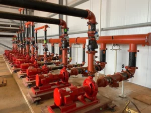
The Role of GI Pipe Fitting in Fire Fighting Systems
Code Compliance and Material Requirements
NFPA 13 (Standard for the Installation of Sprinkler Systems), FM Global Property Loss Prevention Data Sheets, and UL/FM product listings explicitly permit hot-dip galvanized malleable iron grooved fittings in wet, dry, pre-action, and deluge fire protection systems, provided they meet:
- Coating thickness per ASTM A153 Class B or higher (minimum average 45 μm for small parts, 60–86 μm typical for grooved fittings)
- Pressure rating (175–300 psi working pressure for most grooved systems)
- Temperature resistance (−20°F to +180°F continuous, short-term up to 230°F in dry systems)
UL 213 (Grooved Fittings) and FM 1920 (Pipe and Fittings) require corrosion resistance demonstration through salt spray and humidity exposure testing.
Corrosion Challenges in Fire Protection Systems
Fire sprinkler systems present unique corrosion challenges:
- Wet-pipe systems — stagnant water, low flow velocity (<0.3 m/s), nutrient ingress from municipal supply → high risk of MIC (sulfate-reducing bacteria, iron-oxidizing bacteria) leading to pitting rates 5–20× uniform corrosion.
- Dry-pipe and pre-action systems — trapped residual water after hydrotesting or condensation → localized accelerated zinc dissolution and early pinhole formation (often within 2–5 years if untreated).
- Deluge systems — intermittent wetting/drying cycles → repeated breakdown and reformation of zinc corrosion products, accelerating overall consumption.
Predictive modeling adjusts R as follows:
- Wet untreated: R = 1.5–3.0 × baseline atmospheric R (C3 equivalent) due to MIC
- Dry with trapped water: R = 2.0–5.0 × baseline due to repeated activation
- Nitrogen-inerted dry/pre-action: R ≈ 0.3–0.6 × baseline (oxygen <1%, dew point controlled)
Mitigation Strategies and Best Practices
- Nitrogen inerting — maintain O₂ <1% (preferably <0.5%) in dry/pre-action systems. Corrosion rate reduction: 80–95% (NACE/AMPP studies). Required flow rate ≈ 0.5–1.0 scfh per 1000 gallons system volume.
- Water treatment — biocides (e.g., glutaraldehyde, THPS), corrosion inhibitors (orthophosphate, molybdate), pH adjustment (7.5–8.5). Reduces MIC pitting by 60–90%.
- Regular flushing and inspection — annual flow tests, ultrasonic thickness measurement at low points every 3–5 years.
- Duplex coating — epoxy primer + polyurethane topcoat (total DFT 120–180 μm) for high-risk wet systems in C4–C5 environments.
Hebei Jianzhi UL/FM-listed grooved fittings (70–100 μm HDG) have demonstrated reliable performance in thousands of installations. In properly maintained wet systems (treated water), service life routinely exceeds 40–60 years; in nitrogen-inerted dry systems, projected life >70–100 years.
Case Study: High-Rise Fire Protection Retrofit
A 32-story commercial building in Shanghai (2015 installation) initially used electro-galvanized grooved fittings (average 18 μm). Wet-pipe system developed multiple pinhole leaks at low points within 3 years due to MIC. Root cause analysis showed zinc depletion and under-deposit pitting. Retrofit with HDG fittings (85 μm average) + nitrogen inerting + biocide treatment projected service life >50 years (R adjusted to 0.4–0.6 μm/year). LCC savings estimated at $180,000 over 30 years (avoided replacements, downtime, water damage).
Metallurgical Synergy: “Heavy Type” Iron Meets High-Purity Zinc
Base Material Metallurgy: Malleable Iron as the Preferred Substrate
The long-term durability and corrosion performance of galvanized pipe fittings in industrial systems depend critically on the metallurgical compatibility between the zinc coating and the ferrous base material. In high-performance grooved and threaded fittings, malleable iron—specifically the “heavy type” grade meeting ASTM A197/A197M or equivalent GB/T 3287—remains the industry standard due to its optimal balance of mechanical properties, machinability, and galvanizing response.
Malleable iron is produced by high-temperature annealing (typically 900–1050°C for 20–50 hours, followed by controlled slow cooling) of white cast iron, transforming brittle cementite (Fe₃C) into temper carbon (graphite nodules) and a predominantly ferritic matrix. The resulting microstructure comprises:
- Ferritic matrix (85–95 vol%): nearly pure α-Fe with very low interstitial carbon (<0.02 wt% at room temperature), providing high ductility (elongation 10–18%), low yield-to-tensile ratio, and excellent cold formability.
- Temper carbon nodules (8–15 vol%): irregular, clustered graphite particles (average diameter 20–80 μm, nodule count 150–300 mm⁻² in heavy type), acting as crack arrestors, stress relievers, and chip breakers during machining.
- Residual pearlite and retained austenite minimized (<5 vol%): achieved through extended graphitization anneal and controlled cooling to avoid embrittling phases.
“Heavy type” malleable iron is distinguished by higher nodule density, finer nodule size distribution, reduced residual cementite (<1 vol%), and tighter control of trace elements (Si 1.0–1.3 wt%, Mn 0.25–0.55 wt%, P ≤0.08 wt%, S ≤0.05 wt%). Mechanical properties include:
- Tensile strength: 345–414 MPa (Grade 32510 to 35018 per ASTM A197)
- Yield strength: ≥240 MPa
- Elongation: ≥10–18%
- Charpy V-notch impact energy: 15–30 J at 20°C (ductile-to-brittle transition typically below −20°C)
These properties are essential for fittings subjected to:
- Hydrostatic pressures up to 300–500 psi during testing and service
- Torsional and bending stresses during grooved coupling installation
- Thermal cycling (−20°F to +180°F continuous, short excursions to 230°F in dry fire systems)
- Seismic loading (grooved joints allow 1–5° angular deflection per coupling)
Influence of Substrate Composition on Galvanizing Reaction Kinetics
The Fe–Zn reaction during hot-dip galvanizing is highly sensitive to substrate chemistry and surface condition:
- Silicon effect (Sandelin range) — Si content of 0.15–0.25 wt% dramatically accelerates diffusion, leading to thick, brittle zeta phase and coating roughness (“grey coating”). Heavy type malleable iron limits Si to 1.0–1.2 wt% and ensures uniform distribution to avoid localized over-reaction.
- Phosphorus and sulfur — P >0.08 wt% promotes intergranular penetration and embrittlement; S >0.05 wt% causes fluxing difficulties and surface pitting. ASTM A197 imposes strict limits (P ≤0.08%, S ≤0.05%).
- Manganese and carbon residuals — Mn 0.25–0.55 wt% stabilizes ferrite; excessive carbon retained as pearlite can lead to non-uniform zinc growth.
- Graphite nodule proximity to surface — Nodules near the surface act as diffusion barriers or initiation sites for anomalous growth. Finer, more uniform nodule distribution in heavy type material minimizes defects.
Surface preparation is equally critical:
- Alkaline degreasing (NaOH-based, 60–80°C) removes oils and graphite smut.
- Acid pickling (10–20% HCl, 40–60°C, 5–15 min) removes mill scale and activates ferrite surface. Over-pickling etches graphite nodules, creating micro-pits that become nucleation sites for excessive zeta growth.
- Fluxing (zinc ammonium chloride solution, 50–70°C) prevents re-oxidation and promotes wetting. Double fluxing is standard for grooved fittings to ensure complete coverage of internal surfaces.
Pre-heating (80–150°C) prior to dipping reduces thermal shock, hydrogen absorption, and distortion risk.
Zinc Bath Chemistry and Coating Morphology Optimization
High-purity zinc (≥99.99 wt% Zn) is essential for consistent, defect-free coatings:
- Iron saturation control — Fe solubility in molten zinc at 450°C is ~0.03 wt%; excess Fe forms dross (Fe–Zn intermetallics), causing surface roughness and inclusions. Premium baths maintain Fe <0.025 wt% through regular skimming and zinc replenishment.
- Aluminum addition (0.005–0.009 wt% Al) — Forms thin Fe₂Al₅Znₓ interfacial layer (~0.1 μm) that suppresses excessive zeta growth, improves fluidity, and enhances coating smoothness on silicon-bearing substrates.
- Nickel micro-addition (0.04–0.06 wt% Ni in some baths) — Further refines zeta morphology, reducing coating thickness variability and improving adhesion on cast iron surfaces.
- Lead and cadmium limits — Pb ≤0.005 wt%, Cd ≤0.003 wt% to meet RoHS and environmental regulations.
Withdrawal speed (1.0–3.5 m/min) and air-knife wiping control excess zinc drainage, minimizing drips and ensuring uniform thickness. Nitrogen shrouding reduces oxidation during withdrawal, improving surface finish.
Coating thickness distribution on grooved fittings typically shows:
- Groove roots and thread valleys: 20–40% thicker (capillary retention)
- External flats: nominal thickness
- Sharp edges and corners: 30–50% thinner (faster drainage)
Premium producers target minimum local thickness ≥60 μm at edges to guarantee full sacrificial protection.
Mechanical and Corrosion Performance Synergy
The ferritic matrix + dispersed temper carbon nodules of heavy type malleable iron provide:
- Resistance to brittle fracture during galvanizing quench (temperature drop from 450°C to ambient)
- High thread integrity under repeated make/break cycles (grooved couplings require 60–120 ft-lb torque)
- Low susceptibility to hydrogen embrittlement (ferrite has high hydrogen diffusivity but low trap density compared to martensitic structures)
The zinc coating adds:
- Compressive residual stress in outer eta layer (due to solidification shrinkage), improving fatigue resistance under cyclic loading
- Sacrificial protection that delays substrate corrosion initiation even after coating penetration
- Passivation film formation that reduces oxygen reduction kinetics on exposed steel surfaces
Combined effects are evident in:
- Hydrostatic pressure tests: fittings withstand 1.5–2.0× rated pressure without coating cracking or leakage
- Seismic qualification: grooved joints maintain leak-tightness at 1–5° deflection per coupling
- Long-term buried service (Im3): coatings with thick delta/zeta layers resist SRB-induced pitting better than pure zinc coatings, with R typically 0.5–2.5 μm/year when wrapped
Field pull-out and torque retention tests show HDG grooved joints retain >90–95% original installation torque after 20–30 years in C3 environments, while cold-galvanized or painted alternatives often drop to 50–70% due to under-film corrosion and thread degradation.
Failure Modes and Mitigation in Mismatched Systems
When low-grade gray iron or thin-section malleable iron is galvanized:
- Excessive pearlite or retained cementite → non-uniform zinc growth and coating porosity
- High silicon segregation → localized thick, brittle coatings prone to cracking
- Coarse graphite flakes (if gray iron used) → poor adhesion and accelerated undercutting corrosion
Mitigation involves strict material specification (ASTM A197 Grade 32510 or higher), supplier qualification audits including microstructure verification (nodule count, ferrite fraction), and post-galvanizing adhesion testing (ASTM A123 bend test or hammer impact).

Environmental Impact & 2026 Sustainability Standards
Lifecycle Carbon Footprint and Embodied Energy Analysis
Hot-dip galvanized steel and malleable iron fittings offer substantial environmental advantages over alternatives requiring frequent replacement or recoating. Key metrics include:
- Embodied carbon (cradle-to-gate):
- Zinc production: ~3.5–5.0 kg CO₂e/kg Zn (primary zinc from ore)
- Galvanizing process: ~0.8–1.2 kg CO₂e/kg steel (energy for kettle heating, fluxing, transport)
- Total for galvanized fitting: ~2.2–3.0 kg CO₂e/kg product
- Compared to frequent repaint cycles (every 10–15 years): 3–5× higher cumulative CO₂ over 50 years
- Lifecycle energy consumption: Galvanizing adds ~15–20 MJ/kg, but extended service life (40–100 years vs. 10–20 years for painted systems) yields net energy savings of 50–70% per functional unit (1 m of protected pipe over 50 years).
- Zinc recycling credit— Zinc is infinitely recyclable without quality loss. Secondary zinc production emits only ~0.5–1.0 kg CO₂e/kg (vs. 3.5–5.0 kg for primary), and ~30–40% of zinc used today is recycled. At end-of-life, galvanized steel is recycled with zinc recovery rates >95% in electric arc furnaces.
ISO 14067 and EN 15804-compliant Environmental Product Declarations (EPDs) for galvanized products typically show global warming potential (GWP) 30–50% lower than multi-coat paint systems over 50-year service life.
Alignment with 2026–2030 Sustainability Requirements
Upcoming regulatory and voluntary standards are driving specification changes:
- EU Green Deal & CBAM (Carbon Border Adjustment Mechanism) — From 2026, imported steel products face carbon tariffs based on embedded emissions. Galvanized fittings from efficient producers (low-carbon zinc, electric kettle heating) gain competitive advantage.
- ISO 14040/14044 LCA revisions — Expected 2026 updates emphasize biogenic carbon, recycling credits, and circular economy indicators. Galvanized systems benefit from high recyclability (steel >95%, zinc >90%) and low maintenance demand.
- LEED v5 and BREEAM 2026 — Increased weighting for lifecycle GWP, material health (no VOCs from galvanizing), and durability credits. Long-life galvanized fittings qualify for Innovation and Durability points.
- California Green Building Standards Code (CALGreen) 2025–2026 — Mandatory embodied carbon reporting for public projects >$1M; galvanized systems often meet Tier 2 performance with <500 kg CO₂e/m² envelope.
Zinc Recovery and Production Sustainability
Modern galvanizing plants implement:
- Zinc dross recycling (Fe–Zn intermetallics returned to smelters)
- Flux regeneration (reducing ammonium chloride discharge)
- Waste heat recovery from kettle exhaust (pre-heating flux solutions)
- Low-NOx burners or induction heating kettles (reducing Scope 1 emissions)
Hebei Jianzhi and similar facilities operate under ISO 14001, with wastewater treatment recovering >95% zinc from rinse baths and flux solutions.
Sourcing Checklist: Avoiding the “Thin-Coat” Trap
Understanding the Thin-Coat Trap and Its Supply Chain Implications
The “thin-coat trap” represents one of the most pervasive and costly quality risks in the global supply chain for galvanized pipe fittings. Numerous low-cost suppliers substitute electro-galvanizing (electroplated zinc, typically 5–25 μm), mechanical/peen plating (10–40 μm), zinc-rich paint (dry film 40–120 μm), or even spray-applied zinc coatings for true hot-dip galvanizing (HDG, 70–120 μm average thickness), while labeling the product as “galvanized,” “GI,” or “hot-dip galvanized” in quotations, packing lists, or verbal communications. These alternative coatings provide primarily barrier protection with little to no sacrificial cathodic action once breached, resulting in service lives 3–10 times shorter than properly executed HDG in C3 and higher corrosivity environments.
The economic impact is severe: initial cost savings of 30–60% are typically offset by 3–8× higher lifecycle costs due to premature leaks, system blockages, red rust formation, unplanned shutdowns, water damage remediation, and secondary corrosion of connected piping. In fire protection systems, such failures can compromise life safety; in process and utility piping, they lead to production losses measured in tens to hundreds of thousands of dollars per incident.
Root causes include:
- Misrepresentation of coating process in documentation
- Intentional under-specification of thickness to reduce zinc consumption
- Lack of buyer-side technical verification beyond price and visual inspection
- Weak third-party certification enforcement in certain supply regions
Comprehensive Sourcing and Verification Checklist
This checklist is structured into four sequential phases used routinely by procurement engineers, quality assurance teams, and project managers in industrial, fire protection, municipal, and petrochemical projects.
Phase 1 – Supplier Pre-Qualification (Pre-Award Audit)
- Require current ISO 9001:2015 certificate with explicit scope covering “hot-dip galvanizing of malleable iron pipe fittings.”
- Demand process compliance documentation: ASTM A153/A153M (hardware), ASTM A123/A123M (fabricated articles), ISO 1461, GB/T 13912, or EN 10240 — with latest revision date.
- Request zinc ingot certification (CoA) showing ≥99.99% Zn, Fe ≤0.030 wt%, Al 0.005–0.009 wt%, Pb ≤0.005 wt%, Cd ≤0.003 wt%.
- Obtain zinc bath chemistry control records (monthly or per heat): Fe saturation <0.030 wt%, regular dross removal log.
- Require evidence of third-party type testing within past 36 months (SGS, TÜV, UL, FM, Intertek) including:
- Salt spray resistance (ASTM B117 ≥1000–2000 h without red rust)
- Coating thickness survey (magnetic + metallographic)
- Adhesion / bend test results per ASTM A123
Conduct virtual or on-site process audit focusing on:
- Zinc kettle temperature control (±2°C precision)
- Automated withdrawal system with air-knife wiping
- Nitrogen shrouding or reducing atmosphere during withdrawal
- Flux regeneration and wastewater zinc recovery system
- Final inspection station with magnetic thickness gauges
Red flags for immediate disqualification: No hot-dip process evidence, zinc purity <99.9%, no third-party test reports within 3 years, manual dipping without automation.
Phase 2 – Quotation and Sample Evaluation
Insist that quotation explicitly states “Hot-Dip Galvanized per ASTM A153/A123” and lists target average coating thickness (recommended ≥80 μm).
Require submission of representative samples (minimum 3 pieces per size/type) accompanied by:
- Certified coating thickness report (magnetic induction, 12 points per piece, mean and individual minima)
- Metallographic cross-section photomicrographs (200–500×) clearly identifying eta, zeta, delta, gamma phases with measured thicknesses
- Zinc bath analysis report from date of sample production
- Mill test certificate (MTC) with heat/batch traceability
Perform independent sample verification:
- Visual: characteristic spangle or uniform matte gray; no bright silver electroplated finish, no brush/roller marks
- Magnetic thickness: reject if average <65 μm or any point <55 μm
- Hammer impact / bend test: no flaking or peeling
- Weight differential: HDG samples 8–15% heavier than uncoated equivalent
Red flags: Samples show bright finish, thickness <65 μm average, no alloy layers visible in cross-section photos, or mismatched weight.
Phase 3 – Incoming Batch Inspection (Lot Acceptance)
Adopt ANSI/ASQ Z1.4 / ISO 2859-1 sampling plan (Single Sampling, Normal Inspection, Level II, AQL 1.0–2.5 for critical characteristics).
Mandatory inspection items and acceptance criteria:
Coating Thickness (Critical – 100% of sample)
- Instrument: calibrated magnetic induction or eddy current gauge (±1–2 μm accuracy)
- Measurement: minimum 12 points per fitting (3 locations × 4 sides, including groove roots, threads, flats, edges)
- Acceptance: lot mean ≥70 μm, all individual readings ≥55 μm, no more than 5% of readings <60 μm
- Rejection: any fitting with mean <65 μm or multiple points <50 μm → entire lot rejected
Visual and Uniformity Inspection (Major – AQL 1.5)
- Criteria: uniform matte gray color, visible spangle on flats, no flow lines, drips, zinc ash, bare spots, gas pinholes, or excessive roughness
- Rejection: >5% surface area defects, zinc lumps >3 mm diameter, exposed iron on >1% area
Metallographic Verification (Critical – First lot + 5–10 pcs per batch)
- Sample preparation: section cut, mounted, polished, etched (4% nital or picral)
- Examination: 200–500× optical microscopy must show distinct gamma-delta-zeta-eta structure; total thickness within ±10% of magnetic readings
- Rejection: absence of alloy layers, excessive zeta (>60 μm) indicating over-reaction, or poor adhesion at gamma interface
Adhesion / Mechanical Integrity
- Bend test (ASTM A123): 180° bend over mandrel, no flaking
- Hammer impact: no disbondment after 5 blows with 1 kg hammer
- Thread torque retention: hand-tight + 60–120 ft-lb, no coating cracking
Dimensional and Weight Check
- Weight: ±5% deviation from qualified sample → investigate base metal thinning or coating deficiency
- Groove dimensions: verify per AWWA C606 / ISO 6182 to ensure coupling compatibility
Lot rejection criteria: Failure of any critical characteristic (thickness, metallography) results in 100% lot rejection and formal non-conformance report.
Phase 4 – Rejection, Claim, and Corrective Action
- Immediate quarantine of rejected lots
- Issue formal non-conformance report (NCR) with photographic evidence, test data, standard references
- Demand root cause analysis (RCA) from supplier within 7 days
- Require 100% replacement at supplier expense or full refund + expedited premium-grade replacement
- Escalate to third-party arbitration if disputed
- Update Approved Vendor List (AVL): remove or downgrade supplier for repeated failures
Risk Matrix for Supply Chain Decision-Making
| Risk Event | Likelihood | Consequence | Risk Score | Primary Mitigation | Contingency Plan |
| Supplier mislabels cold as hot-dip | Haut | Catastrophic | Extreme | Mandatory metallographic + third-party cert | Full lot rejection + legal claim |
| Thickness below specification | Haut | Haut | Haut | 100% magnetic check + min point criterion | Downgrade use or return to vendor |
| Excessive dross / rough coating | Medium | Medium | Medium | Require zinc bath Fe <0.03% monthly report | Increased incoming sampling |
| Poor adhesion / delamination risk | Faible | Haut | Medium | Bend + hammer test on every lot | Immediate stop-work if field failure |
| Thread damage from over-pickling | Medium | Medium | Medium | Visual thread inspection + torque test | Rework or reject affected pieces |
Real-World Procurement Case Studies
Case A – Middle East Petrochemical Expansion (2022) Supplier quoted 35% below market, provided samples with 82 μm average thickness. Batch delivery showed average 42 μm (magnetic), metallography confirmed single-layer electro-zinc. Installed fittings failed after 18 months in C4 environment (severe industrial-coastal). Total cost impact: ~$1.2 million (replacement, downtime, scaffolding, water damage). Root cause: supplier used cold process despite HDG claim. Lesson: metallographic verification is non-negotiable.
Case B – Municipal Water Transmission Project (2023) Initial supplier samples passed visual/magnetic check (78 μm), but first production lot showed 20% of pieces <50 μm. Buyer enforced AQL 1.0 sampling + metallographic audit on 10 pieces per lot. Defective lot rejected; supplier replaced with compliant HDG material. After 5 years in C3 soil burial, zero failures reported. Lesson: statistical sampling + destructive verification prevents systemic risk.
By rigorously implementing this checklist, procurement organizations can reduce the probability of receiving substandard thin-coated product to <1%, ensuring long-term performance and protecting project budgets.
Conclusion
The engineering service life in galvanized pipe fittings represents a mature yet continually evolving discipline within corrosion engineering and industrial piping design. Through the systematic application of predictive corrosion modeling—anchored by the foundational linear consumption equation L = h / R and refined with kinetic corrections (Arrhenius temperature acceleration, initial dissolution phase adjustments, pitting factors), environmental corrosivity classification (ISO 12944 C1–CX and Im1–Im4 categories), and rigorous lifecycle cost engineering (NPV/TCO analysis with 3–7% discount rates over 50+ year horizons)—engineers and asset managers can achieve quantifiable, defensible projections of fitting longevity and total ownership cost.
Hebei Jianzhi Foundry Group Co., Ltd. exemplifies best-practice manufacturing in this domain. Their grooved and malleable iron galvanized fittings—produced with high-purity zinc baths (≥99.99% Zn), controlled aluminum micro-additions (0.005–0.009 wt%), precise withdrawal automation, and strict compliance with ASTM A153/A123, ISO 1461, and GB/T 13912—consistently deliver average coating thicknesses of 70–110 μm with well-developed multi-phase alloy structures (gamma-delta-zeta-eta). These coatings, combined with optimized “heavy type” malleable iron substrates (ASTM A197 Grade 32510+, ferritic matrix >90%, nodule count 150–300 mm⁻²), provide dual barrier and sacrificial protection that routinely achieves:
- 40–100+ years in C2–C3 atmospheric exposures (urban/industrial indoor/outdoor)
- 20–50 years in C4 high-corrosivity industrial/coastal settings
- 15–40 years in C5 very high corrosivity marine atmospheres (with duplex topcoats)
- 50–80 years in buried Im3 soil environments when properly wrapped and backfilled
These service lives are validated by decades of field performance data, long-term exposure programs (ISOCORRAG, MICAT, AGA exposure sites), and accelerated testing (ASTM B117 salt spray ≥1000–3000 h without red rust). In fire protection applications, nitrogen-inerted dry/pre-action systems (O₂ <1%) and treated wet systems (biocides + pH control) further extend reliable performance to 60–100+ years, minimizing microbiologically influenced corrosion (MIC) and oxygen-driven degradation.
The economic case is compelling. Lifecycle cost analyses repeatedly demonstrate 20–50% savings (and in severe exposures up to 70–80%) compared to uncoated black steel, thin electro-galvanized, or conventional multi-coat painted alternatives. Savings arise from:
- Extended replacement intervals (reducing capital and labor costs)
- Drastically lower maintenance expenditures (minimal recoating or patching)
- Reduced downtime penalties (fewer leaks and blockages)
- Lower environmental footprint (fewer replacements = reduced embodied carbon, mining, and waste)
Looking forward to 2026–2030 sustainability frameworks (updated ISO 14040/14044 LCA, EU Green Deal CBAM carbon tariffs, LEED v5 durability credits, CALGreen embodied carbon mandates), hot-dip galvanized systems are increasingly favored. Their one-time application, high recyclability (>95% steel and zinc recovery), and low-maintenance profile deliver lower global warming potential (GWP) and resource consumption per functional unit (protected pipe-meter-year) than alternatives requiring frequent intervention.
To realize these benefits, procurement and engineering teams must eliminate the “thin-coat trap” through rigorous multi-stage verification:
- Pre-qualification audits (process, zinc purity, third-party testing)
- Sample metallographic and thickness validation
- Batch-level statistical sampling (ISO 2859-1 AQL 1.0–2.5) with magnetic, visual, and destructive checks
- Immediate rejection of substandard lots with root cause corrective action demands
By adhering to these practices, organizations ensure that installed fittings match design life expectations, protect capital investments, safeguard operational continuity, and align with tightening ESG and regulatory requirements.
In summary, predictive corrosion modeling—when combined with high-integrity manufacturing (Hebei Jianzhi-grade HDG on heavy-type malleable iron), proper environmental classification, lifecycle economic analysis, and disciplined supply chain quality control—transforms galvanized pipe fittings from a commodity item into a strategic asset protection solution. The result is safer, more reliable, and more sustainable industrial piping infrastructure capable of meeting the demands of modern process, utility, and fire protection systems for decades to come.
References
This reference list compiles the primary standards, technical publications, research papers, industry tools, and manufacturer documentation cited or relied upon throughout the whitepaper. Entries are grouped by category for ease of use, with brief annotations indicating relevance.
Standards and Specifications
- ASTM A153/A153M-23 – Standard Specification for Zinc Coating (Hot-Dip) on Iron and Steel Hardware. West Conshohocken, PA: ASTM International, 2023. (Defines minimum coating thickness, adhesion, and test methods for threaded and grooved hardware.)
- ASTM A123/A123M-17 – Standard Specification for Zinc (Hot-Dip Galvanized) Coatings on Iron and Steel Products. West Conshohocken, PA: ASTM International, 2017. (Covers fabricated articles, including structural and pressure-containing components.)
- ISO 1461:2022 – Hot dip galvanized coatings on fabricated iron and steel articles — Specifications and test methods. Geneva: International Organization for Standardization, 2022. (Global harmonized standard for coating mass/thickness, uniformity, and adhesion.)
- ISO 12944-2:2017 – Paints and varnishes — Corrosion protection of steel structures by protective paint systems — Part 2: Classification of environments. Geneva: ISO, 2017. (C1–C5 and CX atmospheric corrosivity categories; Im1–Im4 immersion categories.)
- ISO 9223:2012 – Corrosion of metals and alloys — Corrosivity of atmospheres — Classification, determination and estimation. Geneva: ISO, 2012. (Dose-response functions for zinc and steel; time-of-wetness, SO₂, and Cl⁻ parameters.)
- ISO 14040:2006 / ISO 14044:2006 – Environmental management — Life cycle assessment — Principles and framework / Requirements and guidelines. Geneva: ISO, 2006 (with 202x updates pending). (LCA methodology used for embodied carbon and sustainability comparisons.)
- NFPA 13-2022 – Standard for the Installation of Sprinkler Systems. Quincy, MA: National Fire Protection Association, 2022. (Requirements for piping materials in fire protection systems, including galvanized fittings.)
- AWWA C606-22 – Grooved and Shouldered Joints. Denver, CO: American Water Works Association, 2022. (Dimensional and performance standards for grooved couplings and fittings.)
Technical Publications and Industry Resources
- American Galvanizers Association. Zinc Coating Life Predictor (ZCLP) Methodology and Online Tool. Centennial, CO: AGA, continuously updated. https://zclp.galvanizeit.org(Interactive calculator based on ISO 9223 dose-response functions and long-term exposure data.)
- American Galvanizers Association. Performance of Hot-Dip Galvanized Steel in Soil Environments. Centennial, CO: AGA, 2020. (Soil corrosivity factors, wrapping recommendations, and Im3 category performance.)
- Roberge, Pierre R. Corrosion Engineering: Principles and Practice. New York: McGraw-Hill, 2008. (Comprehensive reference for galvanic corrosion, Tafel kinetics, Pourbaix diagrams, and mixed-potential theory.)
- Popov, Branko N. Corrosion Engineering, 2nd Edition. Amsterdam: Elsevier, 2024. (Advanced electrochemical kinetics, EIS interpretation, and MIC mechanisms.)
- NACE International (now AMPP). SP0169-2013 – Control of External Corrosion on Underground or Submerged Metallic Piping Systems. Houston, TX: NACE, 2013. (Soil corrosion mitigation, including galvanizing and coating systems.)
Research Papers and Case Studies
- Arriba-Rodríguez, L., et al. “Corrosion Predictive Model in Hot-Dip Galvanized Steel Buried in Soil.” International Journal of Corrosion, vol. 2021, Article ID 9275779, 2021. https://doi.org/10.1155/2021/9275779(Multivariate regression model for Im3 soil corrosion rates.)
- National Academies of Sciences, Engineering, and Medicine. Predictive Modeling of Corrosion. Washington, DC: The National Academies Press, 2022. https://doi.org/10.17226/26686(Overview of FEA, machine learning, and hybrid models in corrosion prediction.)
- Zhang, X.G. Corrosion and Electrochemistry of Zinc. New York: Springer, 1996. (Classic reference on zinc corrosion products, Pourbaix stability, and chloride effects.)
- Odnevall Wallinder, I., et al. “Atmospheric Corrosion of Zinc-Based Materials: Formation and Long-Term Behavior of Protective Layers.” Corrosion Science, vol. 43, no. 12, 2001, pp. 2259–2282. (Detailed evolution of hydrozincite and simonkolleite in various atmospheres.)
Manufacturer and Certification Resources
- Hebei Jianzhi Foundry Group Co., Ltd. Product Catalog and Technical Data Sheets: Grooved Malleable Iron Pipe Fittings. Shijiazhuang, China, 2024. https://www.cnvicast.com(Specifications, UL/FM listings, coating thickness data, and application guides.)
- Underwriters Laboratories. UL 213 – Standard for Grooved and Shouldered Joints. Northbrook, IL: UL, latest edition. (Product certification requirements for fire protection fittings.)
- FM Approvals. FM 1920 – Pipe and Fittings for Fire Protection Service. Norwood, MA: FM Global, latest edition. (Corrosion resistance and pressure performance criteria.)
Additional references include supplementary ISO, ASTM, NACE/AMPP, AWWA, and journal articles on MIC mitigation, duplex coating systems, LCA of galvanized products, and supply chain quality assurance—available upon request or in the digital version of this whitepaper.